Involute Gear Cutter Chart
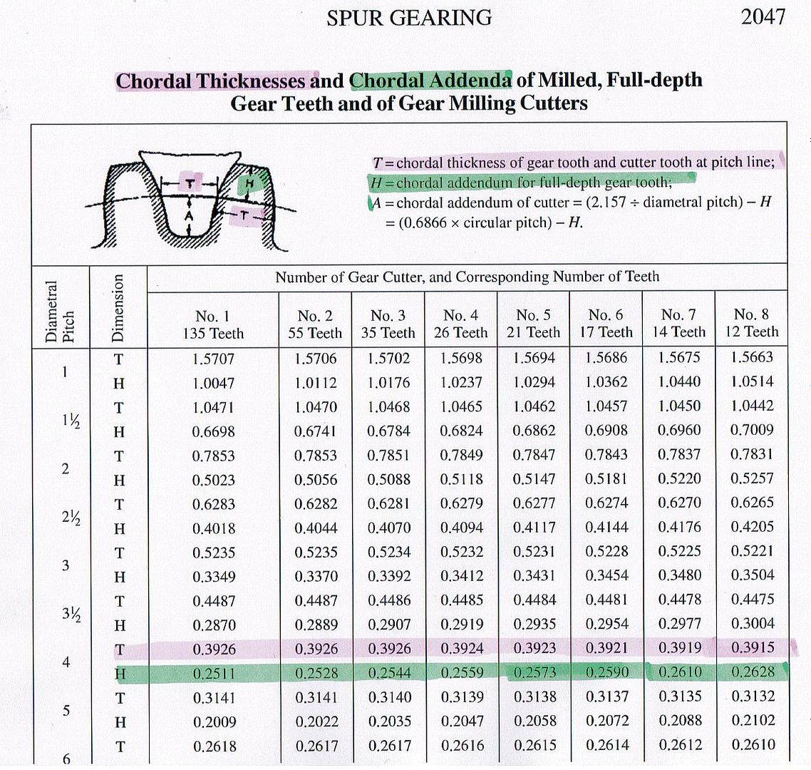
Involute Gear Cutter Chart - With the involute function many geometric gear parameters can be calculated. Web gear design and engineering. Gear shapers can not only generate external gears but also generate internal gear teeth. Determine the pitch of the gear you're cutting. Web figure 3.5 illustrates how an involute gear tooth profile is generated. Web the curve is generated by a tool called an involute gear cutter, which cuts the gear teeth from a gear blank. The edge will take on the profile of a tooth space and it becomes the gear cutter. The cutter is designed to generate the correct involute shape for a given module or pitch of the gear. Web use the selection chart to help you to easily determine the cutter number, based on the number of teeth on your gear, and more. Pitch or module, pressure angle and tooth count. Between 6 and 50) diametral pitch teeth/in. Design 10'f involute gear 'teeth by fellows 'corporation fig. With the involute function many geometric gear parameters can be calculated. All angles for the involute function must always be given in radians! Select the cutter that matches your gear's pitch and number of teeth. Determine the pitch of the gear you're cutting. Find comprehensive reference tables that list: Download a free chart to compare cutter number and tooth range for metric and imperial gears. Web learn how to choose a gear cutter based on the pitch, pressure angle, and number of teeth of the gear. Web gear modules range from 0.004 to 100 millimeters,. Geometry of involute gears | what is an involute | module | pitch circle | simply explained. This is my attempt at explaining how to choose the right cutter for making gears. A gear wheel can be fully defined with as few as two parameters: Indicating that the involute has its origin at the base drde, but is not limited. Web involute cutters are designed to withstand extreme hardness and working conditions where temperatures go beyond 600 degrees. In designing involute gear teeth. Of teeth + 2) / od. Web figure 3.5 illustrates how an involute gear tooth profile is generated. Web φ = tan(α) − α. In stock and ready to ship. As this is undesirable a standard was introduced using a series of eight cutters to cover the range. In designing involute gear teeth. Gear shapers with pinion cutters can also be used to generate involute gears. I basically cover diametral pitch, module, and how. Find comprehensive reference tables that list: The following are equations and engineering design calculator to determine critical design dimensions and features for an involute gear. Inv(α) = tan(α) − α = φ involute function. To cut gears with different number of teeth a different cutter is required for each gear. The teeth are simply thinner at the back than at. Mon base circle, so that the involute profile extends along the whole length of the tooth from the front face to the back of the cutter. All angles for the involute function must always be given in radians! Round to the nearest whole number. Web φ = tan(α) − α. The teeth are simply thinner at the back than at. Indicating that the involute has its origin at the base drde, but is not limited in length. In stock and ready to ship. Web gear design and engineering. In designing involute gear teeth. The power transmission capability can reach up to 100,000 kilowatts, and the rotational speed can be as high as 100,000 revolutions per minute. The cutter is designed to generate the correct involute shape for a given module or pitch of the gear. Web gear modules range from 0.004 to 100 millimeters, the gear diameter can range from 1 millimeter to 150 meters. That is, a gear's profile does not depend on the gear it mates with. These are listed in table 1. Geometry. The power transmission capability can reach up to 100,000 kilowatts, and the rotational speed can be as high as 100,000 revolutions per minute. Number of cutter will cut gears from number of cutter will cut gears from 1 135 to a rack 5 21 to 25 2 55 to 134 6 17. The highest circumferential speed can reach up to. This is my attempt at explaining how to choose the right cutter for making gears. The highest circumferential speed can reach up to 300 meters per second. Design 10'f involute gear 'teeth by fellows 'corporation fig. Between 6 and 50) diametral pitch teeth/in. These are listed in table 1. Web figure 3.5 illustrates how an involute gear tooth profile is generated. In stock and ready to ship. Of teeth + 2) / od. The edge will take on the profile of a tooth space and it becomes the gear cutter. Involute toothing is often used in mechanical engineering for gears, as it offers favorable meshing and is easy to produce. Select the cutter that matches your gear's pitch and number of teeth. 2.5, 3, 4, 5, 6, 8, 10, 12, 16, 20, 24, 32, 40, 48; Pitch or module, pressure angle and tooth count. Use the following key parameters: The cutter is designed to generate the correct involute shape for a given module or pitch of the gear. Web φ = tan(α) − α.
How to select involute gear cutter terrawes
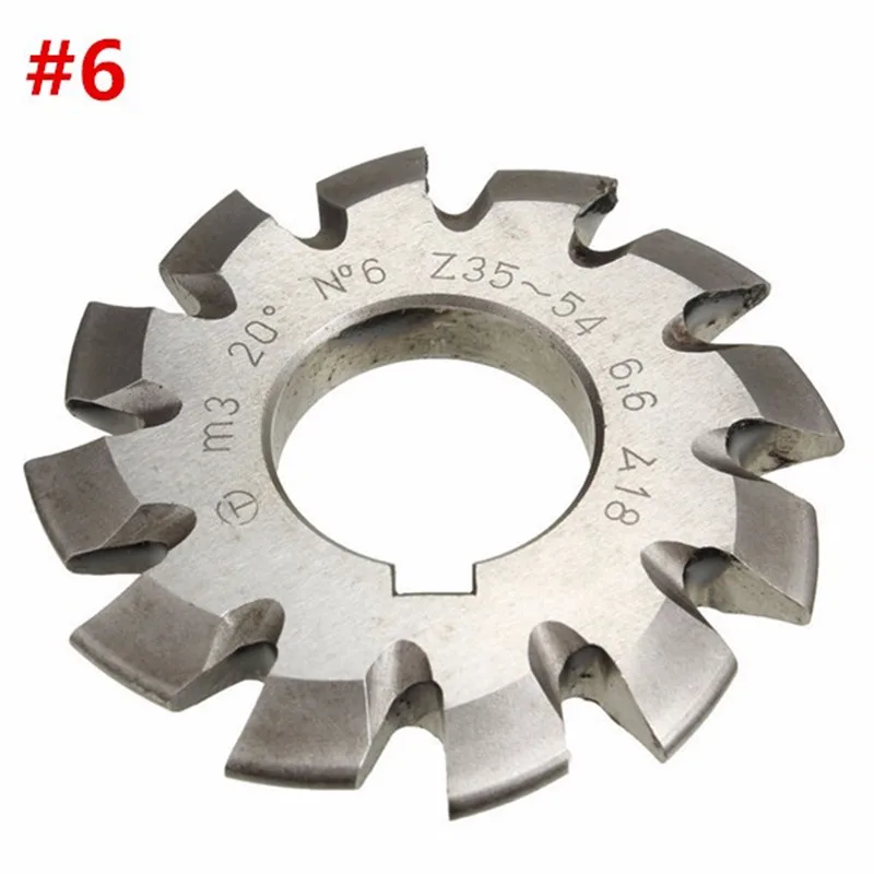
How to select involute gear cutter terrawes
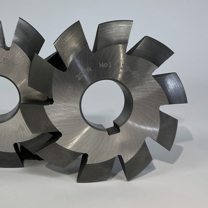
Involute Gear Cutter Chart ubicaciondepersonas.cdmx.gob.mx
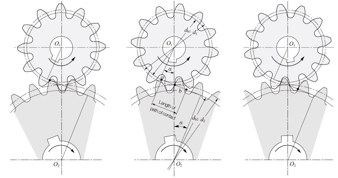
Involute Gear Profile KHK Gears
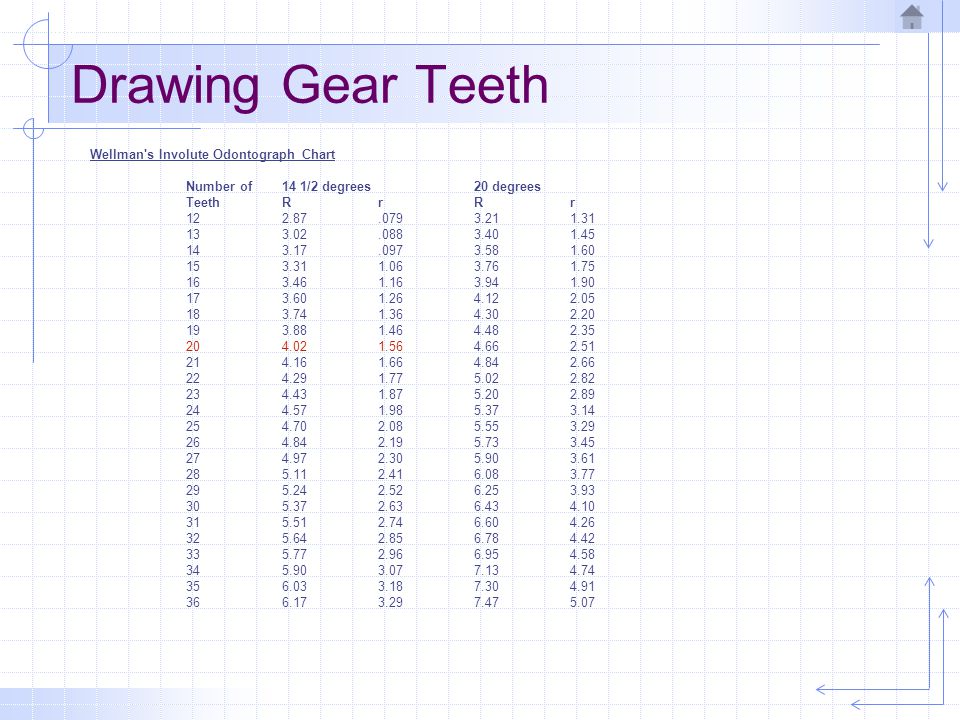
Involute Gear Cutter Chart vlr.eng.br

Table 4. Involute Gear Milling Cutters.
Gears & Cutting Gears

How to Choose a Gear Cutter Involute Gear Cutter Chart Evolvent Des
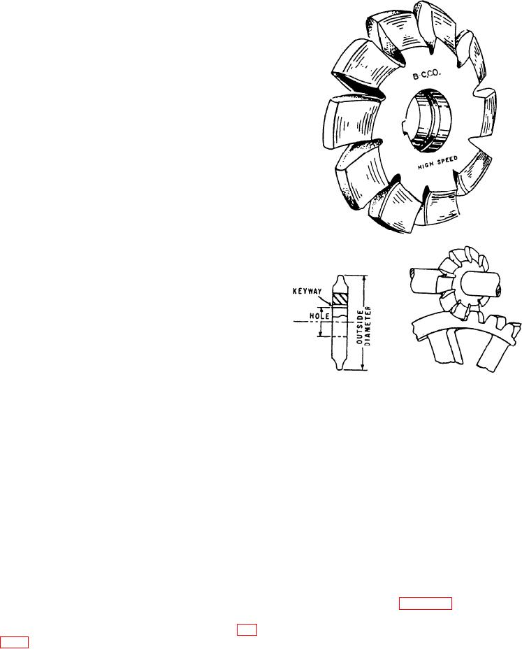
Figure 1030.Involute gear cutter.

Cutter Adapter Charts gearworksinc
In Designing Involute Gear Teeth.
Find Comprehensive Reference Tables That List:
Web Use The Selection Chart To Help You To Easily Determine The Cutter Number, Based On The Number Of Teeth On Your Gear, And More.
The Power Transmission Capability Can Reach Up To 100,000 Kilowatts, And The Rotational Speed Can Be As High As 100,000 Revolutions Per Minute.
Related Post: