Belt Deflection Chart
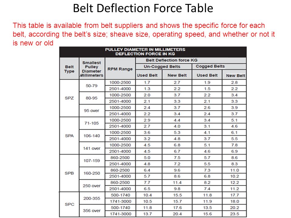
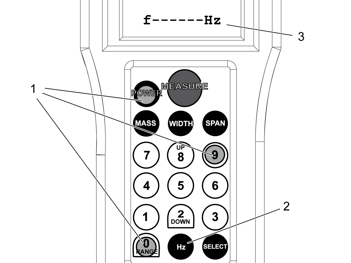
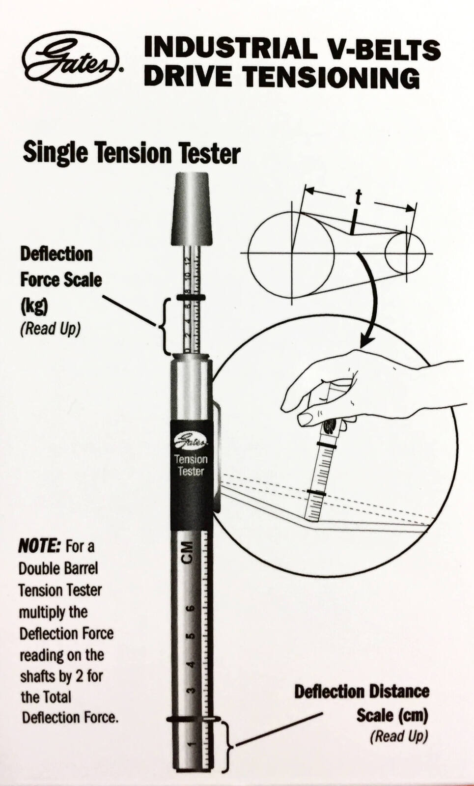
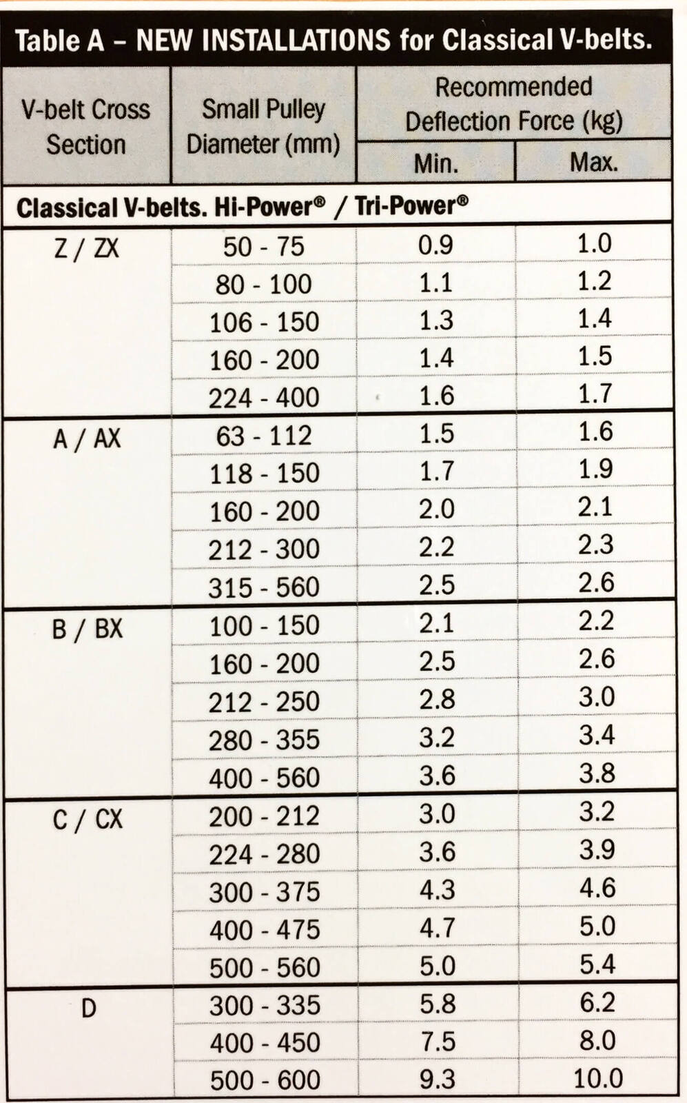
Belt Deflection Chart - Web this paper presents a thorough explanation of geometric, loading and deflection relationships of reinforced urethane timing belts. At the center of the belt span apply a force p (see figure #2) at the midpoint of the belt span, in a direction perpendicular to the span, until the belt is. For comprehensive product information see gates industrial power transmission systems catalog no. Web belt installation tension is generally, measured in the following ways: Be careful not to trap fingers ! Web first, the effective belt tension (te) must be calculated. So, for a 32” span, the deflection amount would be 32/64” or 1/2”. Per inch of span length (for example, a 32 ! Web belt pitch belt width deflection force. The recommended force can be. Measure the span length (t) in cm. Jk fenner has developed an. Proper belt tension ensures optimum performance of a vehicle's accessory belt drive system. For comprehensive product information see gates industrial power transmission systems catalog no. 2] rotate the pulleys a few revolutions to allow the belts to sit correctly in the pulley grooves. Per inch of span length (for example, a 32 ! Measure the belt span (see sketch). Apply force at right angles to the center of the. The force f to apply is shown, per belt, in the table to. Web calculate the deflection distance by: See tables below for correct deflection force. Specifically the target tension is broken into two values deflection force and. Measure the belt span (see sketch). 8mm (14mm) 20mm 30mm 50mm 85mm 2 to 4 lbs 3 to 6 lbs 7 to 11 lbs 11 to 19 lbs. The recommended force can be. The tensionrite® meter , from the trusted brand of. Select from the dropdown options below to find the. Belt deflection and its force. For comprehensive product information see gates industrial power transmission systems catalog no. The force f to apply is shown, per belt, in the table to. 2] rotate the pulleys a few revolutions to allow the belts to sit correctly in the pulley grooves. See tables below for correct deflection force. For comprehensive product information see gates industrial power transmission systems catalog no. Position bottom of the large “o” ring on the span scale at the measured belt span. Web by measuring the deflection of the. Be careful not to trap fingers ! For comprehensive product information see gates industrial power transmission systems catalog no. Note from figure 26 that the deflection distance is always 1/64 ! The recommended force can be. Web calculate the deflection distance by: Determine the deflection distance by dividing span length. Web calculate the deflection distance by: Web belt installation tension is generally, measured in the following ways: Belt span tension can be measured by deflecting a belt span 1/64 per inch (0.4 mm per 25. Web the amount of force required to deflect the belt should compare with the deflection forces noted. Proper belt tension ensures optimum performance of a vehicle's accessory belt drive system. Web belt installation tension is generally, measured in the following ways: See tables below for correct deflection force. Web the amount of force required to deflect the belt should compare with the deflection forces noted in the chart below. The greater the misalignment, the greater the chance. Web by measuring the deflection of the timing belt with a known force the required tension can be applied. For comprehensive product information see gates industrial power transmission systems catalog no. Web the amount of force required to deflect the belt should compare with the deflection forces noted in the chart below. It covers valuable background for the. The force. Be careful not to trap fingers ! Per inch of span length (for example, a 32 ! Measure the belt span length and calculate the desired deflection distance (1/64” per inch of span length) using a spring scale,. Determine the deflection distance by dividing span length. For comprehensive product information see gates industrial power transmission systems catalog no. When you install a new set of belts, use the gauge to establish correct tension. Belt drive design is key in obtaining optimum performance and durability in transmission systems. Web by measuring the deflection of the timing belt with a known force the required tension can be applied. Measure the belt span (see sketch). Be careful not to trap fingers ! Select from the dropdown options below to find the. Apply force at right angles to the center of the. See tables below for correct deflection force. Te is the sum of the tension required to move the empty belt (tc), the tension required to move the load horizontally. Web measuring belt tension by deflection measuring belt tension by deflection evaluates the force needed to achieve a given belt deflection. Belt deflection and its force. Per inch of span length (for example, a 32 ! Web first, the effective belt tension (te) must be calculated. Note from figure 26 that the deflection distance is always 1/64 ! The recommended force can be. Web the amount of force required to deflect the belt should compare with the deflection forces noted in the chart below.
Belt Deflection Chart
Gates V Belt Tension Chart
Belt Deflection Chart A Visual Reference of Charts Chart Master
Belt Tension Deflection Table Belt (Mechanical) Manufactured Goods

Reliable VBelt Drive Operation 20170602 Engineered Systems Magazine
V Belt Deflection Chart Labb by AG
V Belt Deflection Chart Labb by AG
Belt Deflection Belt Tension Chart ubicaciondepersonas.cdmx.gob.mx
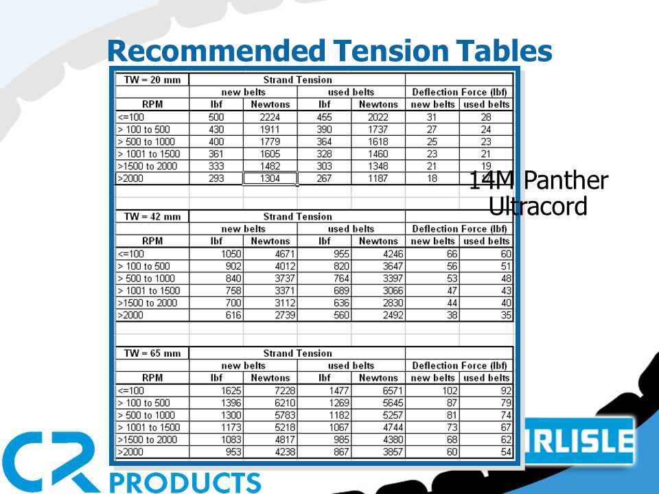
V Belt Deflection Chart Labb by AG

v belt deflection chart Medi Business News
Web Belt Installation Tension Is Generally, Measured In The Following Ways:
Belt Span Tension Can Be Measured By Deflecting A Belt Span 1/64 Per Inch (0.4 Mm Per 25.
Web This Paper Presents A Thorough Explanation Of Geometric, Loading And Deflection Relationships Of Reinforced Urethane Timing Belts.
Specifically The Target Tension Is Broken Into Two Values Deflection Force And.
Related Post:
