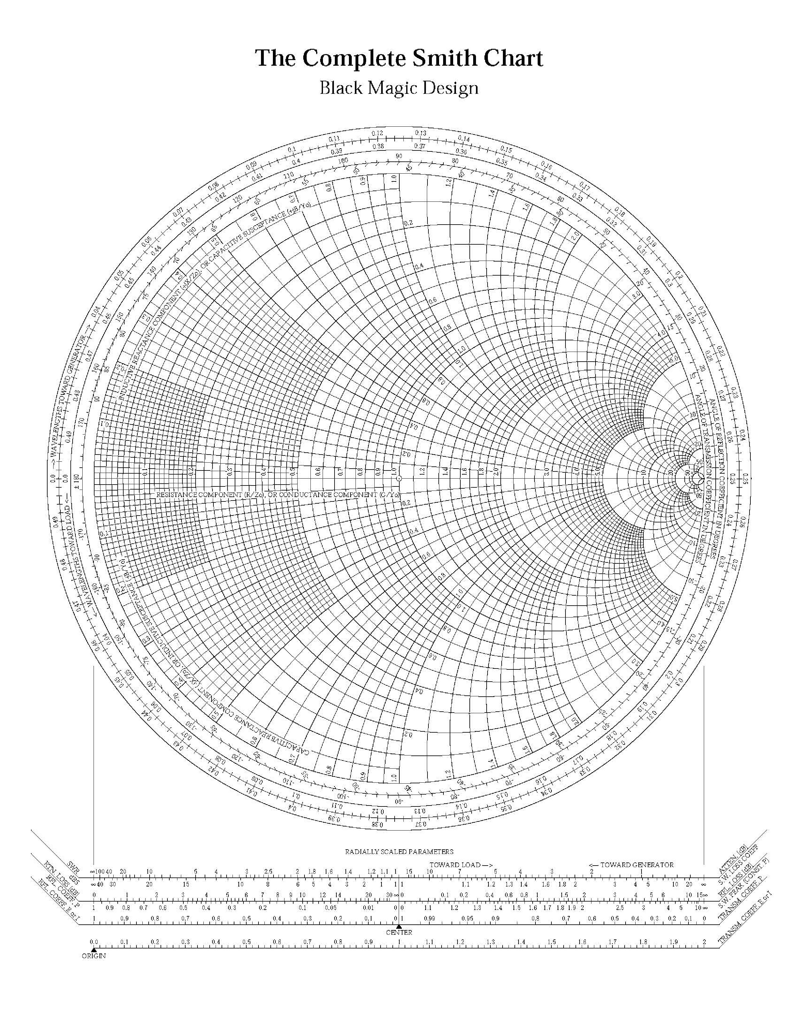
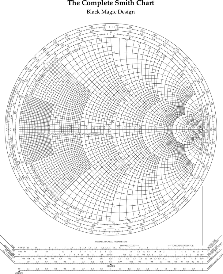
The Complete Smith Chart
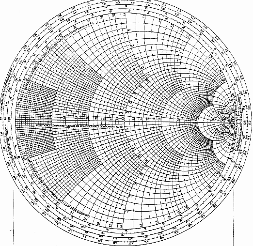
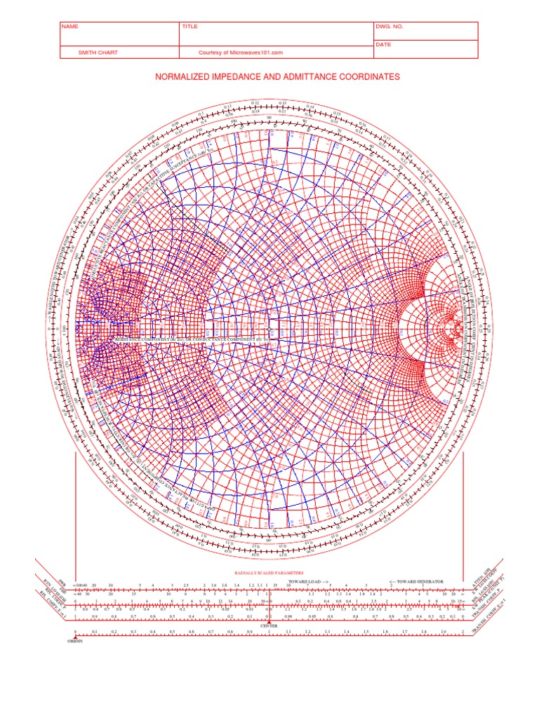
The Complete Smith Chart - Web plot complex impedances on a smith chart. Web the smith chart presents a large amount of information in a confined space and interpretation, such as applying appropriate signs, is required to extract values. Web the smith chart was invented by phillip smith in 1939 in order to provide an easily usable graphical representation of the complex reflection coefficient γ and reading of the associated complex terminating impedance. Web the smith chart presents a large amount of information in a confined space and interpretation, such as applying appropriate signs, is required to extract values. Γis defined as the ratio of electrical field strength of the reflected versus forward travelling wave. Complex numbers with positive real parts map inside the circle. Web the complete smith chart 10 resistan e component r or condu black magic design 012 ance component( radially scaled parameters toward. It consists of two sets of circles for plotting various parameters of mismatched transmission lines. Web the smith chart is a graphical tool for determination of the reflection coefficient and impedance along a transmission line. Web 0.1 0.1 0.1 0.2 0.2 0.2 0.3 0.3 0.3 0.4 0.4 0.4 0.5 0.5 0.5 0.6 0.6 0.6 0.7 0.7 0.7 0.8 0.8 0.8 0.9 0.9 0.9 1.0 1.0 1.0 1.2 1.2 1.2 1.4 1.4 1.4 1.6 1.6 1.6 1.8 1.8 1. An example using the avago. Web from mathematical point of view, the smith chart is simply a representation of all possible complex impedances with respect to coordinates defined by the reflection coefficient. Determine swr from the smith chart. Web the smith chart is a powerful graphical tool that is extensively used by rf engineers to rapidly determine how a given. Determine the impedance of a load at the end of a transmission line. It is a most useful and powerful graphical solution to the transmission line problem. Web the smith chart is a graphical tool that is used in rf transmission line design and electrical engineering. It represents complex impedance values on a polar plot, which allows experts to visualize. Web the smith chart is a sophisticated graphic tool for solving transmission line problems. It is used to express and analyze the impedance of electronic components versus the operating frequency. Web the complete smith chart 10 resistan e component r or condu black magic design 012 ance component( radially scaled parameters toward. The domain of definition of the reflection coefficient. Web the smith chart presents a large amount of information in a confined space and interpretation, such as applying appropriate signs, is required to extract values. The smith chart provides a very useful graphical aid to the analysis of these problems. It is a most useful and powerful graphical solution to the transmission line problem. In introduction to using the. Web the smith chart is a graphical tool that is used in rf transmission line design and electrical engineering. It is used to express and analyze the impedance of electronic components versus the operating frequency. An example using the avago. Web the complete smith chart provides a visual map of complex impedance and reflection coefficients. It represents complex impedance values. Those with negative real parts map outside the. Web the smith chart is a graphical tool used extensively for wired and wireless design at rf frequencies. Web 0.1 0.1 0.1 0.2 0.2 0.2 0.3 0.3 0.3 0.4 0.4 0.4 0.5 0.5 0.5 0.6 0.6 0.6 0.7 0.7 0.7 0.8 0.8 0.8 0.9 0.9 0.9 1.0 1.0 1.0 1.2 1.2 1.2. It can be thought of as a polar reflection coefficient chart with overlaid impedance curves. Γis defined as the ratio of electrical field strength of the reflected versus forward travelling wave. From the beginning of world war ii until the development of digital computers for engineering problems, the smith chart was the dominant tool for microwave engineers. It is a. Web plot complex impedances on a smith chart. From the beginning of world war ii until the development of digital computers for engineering problems, the smith chart was the dominant tool for microwave engineers. Determine swr from the smith chart. It is a useful graphical aid for matching impedances of circuit elements, to optimize their performance. It can be thought. Web a network analyzer ( hp 8720a) showing a smith chart. It is a most useful and powerful graphical solution to the transmission line problem. From the beginning of world war ii until the development of digital computers for engineering problems, the smith chart was the dominant tool for microwave engineers. Web the smith chart presents a large amount of. Web the smith chart is a graphical tool used extensively for wired and wireless design at rf frequencies. Web 0.1 0.1 0.1 0.2 0.2 0.2 0.3 0.3 0.3 0.4 0.4 0.4 0.5 0.5 0.5 0.6 0.6 0.6 0.7 0.7 0.7 0.8 0.8 0.8 0.9 0.9 0.9 1.0 1.0 1.0 1.2 1.2 1.2 1.4 1.4 1.4 1.6 1.6 1.6 1.8 1.8. It is a most useful and powerful graphical solution to the transmission line problem. It is used to express and analyze the impedance of electronic components versus the operating frequency. Web the chart known as the smith chart was the work of philip smith and mizuhashi tosaku, who seem to have developed it independently of each other. Those with negative real parts map outside the. It is a useful graphical aid for matching impedances of circuit elements, to optimize their performance. Web the smith chart presents a large amount of information in a confined space and interpretation, such as applying appropriate signs, is required to extract values. Web the smith chart is a useful graphical tool to convert between impedances and reflection coefficients. Web the smith chart was developed by the electrical engineer phillip h. An example using the avago. Web the smith chart presents a large amount of information in a confined space and interpretation, such as applying appropriate signs, is required to extract values. Web a network analyzer ( hp 8720a) showing a smith chart. Web the smith chart is a graphical tool used extensively for wired and wireless design at rf frequencies. Web the smith chart is a graphical tool that is used in rf transmission line design and electrical engineering. Web the smith chart is a graphical tool for determination of the reflection coefficient and impedance along a transmission line. From the beginning of world war ii until the development of digital computers for engineering problems, the smith chart was the dominant tool for microwave engineers. The domain of definition of the reflection coefficient is a.
The Smith Chart A Vital Graphical Tool DigiKey
Printable Smith Chart

How to use smith chart jeshn

The Smith Chart. Infographics and Data Visualizations Pinterest

Smith Chart Ximera

The complete smith chart pdf humaninput

Printable Smith Chart

Free The Complete Smith Chart PDF 109KB 1 Page(s) Smith chart

The Complete Smith Chart Black Magic Design InfoGraphic Smith

Impedance and admittance smith chart pdf fobxex
The Smith Chart Provides A Very Useful Graphical Aid To The Analysis Of These Problems.
Web From Mathematical Point Of View, The Smith Chart Is Simply A Representation Of All Possible Complex Impedances With Respect To Coordinates Defined By The Reflection Coefficient.
It Represents Complex Impedance Values On A Polar Plot, Which Allows Experts To Visualize And Manipulate Impedance Changes.
Web The Complete Smith Chart Provides A Visual Map Of Complex Impedance And Reflection Coefficients.
Related Post:
