Refrigeration Cycle Chart
Refrigeration Cycle Chart - The refrigeration cycle is the heart of the hvacr industry. Component #2 in this refrigeration cycle diagram is the condenser. This sequence runs periodically and always achieves the initial state (cyclic process). L h hp carnot h l f carnot t t cop t t cop 1. Web refrigeration cycle is thermodynamic cycle to generate refrigerating effect with use of evaporator, compressor, condenser & expansion valve. Web the ideal basic refrigeration cycle consists of four components, connected by piping with refrigerant flowing through the system. Web refrigeration cycle diagram: The compressor, condenser, expansion valve, and evaporator. Compression, condensation, expansion, and evaporation. The condenser accepts the gas from the compressor and, through some cooling medium, condenses it to a high pressure, cool temperature liquid. Web the basic refrigeration cycle diagram illustrates the process through which a refrigeration system cools and dehumidifies the air. Web in the refrigeration process there are two sections which produce a pressure difference: The refrigeration cycle is the main basic cycle for all air conditioning and refrigeration equipment. This sequence runs periodically and always achieves the initial state (cyclic process).. Condenser 3 compressor expansion device. The diagram outlines the four main components of the system: Ordinate axis) and enthalpy (i.e. Conventional and magnetic refrigeration cycles use different physical effects to cool things off. Web the rate of flow through the system will depend on the size of the unit, and the operating pressures will depend on the refrigerant being used. These processes take place respectively in the compressor, condenser, expansion valve, and evaporator. In refrigeration, the state variables such as pressure, temperature and density are important as is the dependence of these state variables on each. Web the simple refrigeration cycle consists of four main processes: L h hp carnot h l f carnot t t cop t t cop. Conventional and magnetic refrigeration cycles use different physical effects to cool things off. Condenser 3 compressor expansion device. A basic refrigeration cycle consists of 4 major components: Here we explain it in simple, understandable terms and diagrams! Web refrigeration cycle diagram: Component #2 in this refrigeration cycle diagram is the condenser. Web refrigeration cycle is thermodynamic cycle to generate refrigerating effect with use of evaporator, compressor, condenser & expansion valve. The liquid line feeds the thermal expansion valve or device where the liquid expands and flashes to a gas and cools. L h hp carnot h l f carnot t t. Component #2 in this refrigeration cycle diagram is the condenser. The coefficient of performance for carnot refrigerators and heat pumps are: The refrigeration cycle is the main basic cycle for all air conditioning and refrigeration equipment. Web the refrigeration cycle is a science that involves many factors and variables. The refrigeration cycle can be described by a sequence of state. Abscissa axis) as shown in fig. The red dots inside the piping represent discharge vapor. Web the simple refrigeration cycle consists of four main processes: A basic refrigeration cycle consists of 4 major components: In refrigeration, the state variables such as pressure, temperature and density are important as is the dependence of these state variables on each. Web refrigeration cycle diagram: L h hp carnot h l f carnot t t cop t t cop 1. Figure 13 shows the components in the cycle and figure 14 shows the basic cycle on the ph diagram. The diagram outlines the four main components of the system: Each component plays a crucial role in the cycle. Web refrigeration cycle diagram: The liquid region represents the refrigerant’s state during the condensation process, while the boiling region represents the refrigerant’s state during the evaporation process. The reversed carnot cycle is the most efficient refrigeration cycle operating between two specified temperature levels. The red dots inside the piping represent discharge vapor. How it works and what you need to. Vapour compression refrigeration system is the most widely used refrigeration system. It sets the highest theoretical cop. Web the ideal basic refrigeration cycle consists of four components, connected by piping with refrigerant flowing through the system. A basic refrigeration cycle consists of 4 major components: Web the refrigeration cycle is a simple but amazingly clever and useful process. The diagram outlines the four main components of the system: In refrigeration, the state variables such as pressure, temperature and density are important as is the dependence of these state variables on each. The reversed carnot cycle is the most efficient refrigeration cycle operating between two specified temperature levels. Ordinate axis) and enthalpy (i.e. Web the rate of flow through the system will depend on the size of the unit, and the operating pressures will depend on the refrigerant being used and the desired evaporator temperature. Web refrigeration cycle diagram: Web refrigeration cycle flow chart. L h hp carnot h l f carnot t t cop t t cop 1. Web the refrigeration cycle is a simple but amazingly clever and useful process. Web the basic refrigeration cycle diagram illustrates the process through which a refrigeration system cools and dehumidifies the air. Web in this hvac video, i give a tutorial to explain the refrigeration cycle with superheat and subcooling step by step, detailed and concise! Web the simple refrigeration cycle consists of four main processes: Knowing the refrigeration cycle well will ensure air conditioner success during service, installation, and maintenance. These processes take place respectively in the compressor, condenser, expansion valve, and evaporator. Web in the refrigeration process there are two sections which produce a pressure difference: This chart acts as a tool in understanding the behaviour of a refrigerant.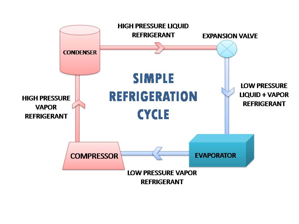
The 4 Main Important Components of Refrigeration Cycle
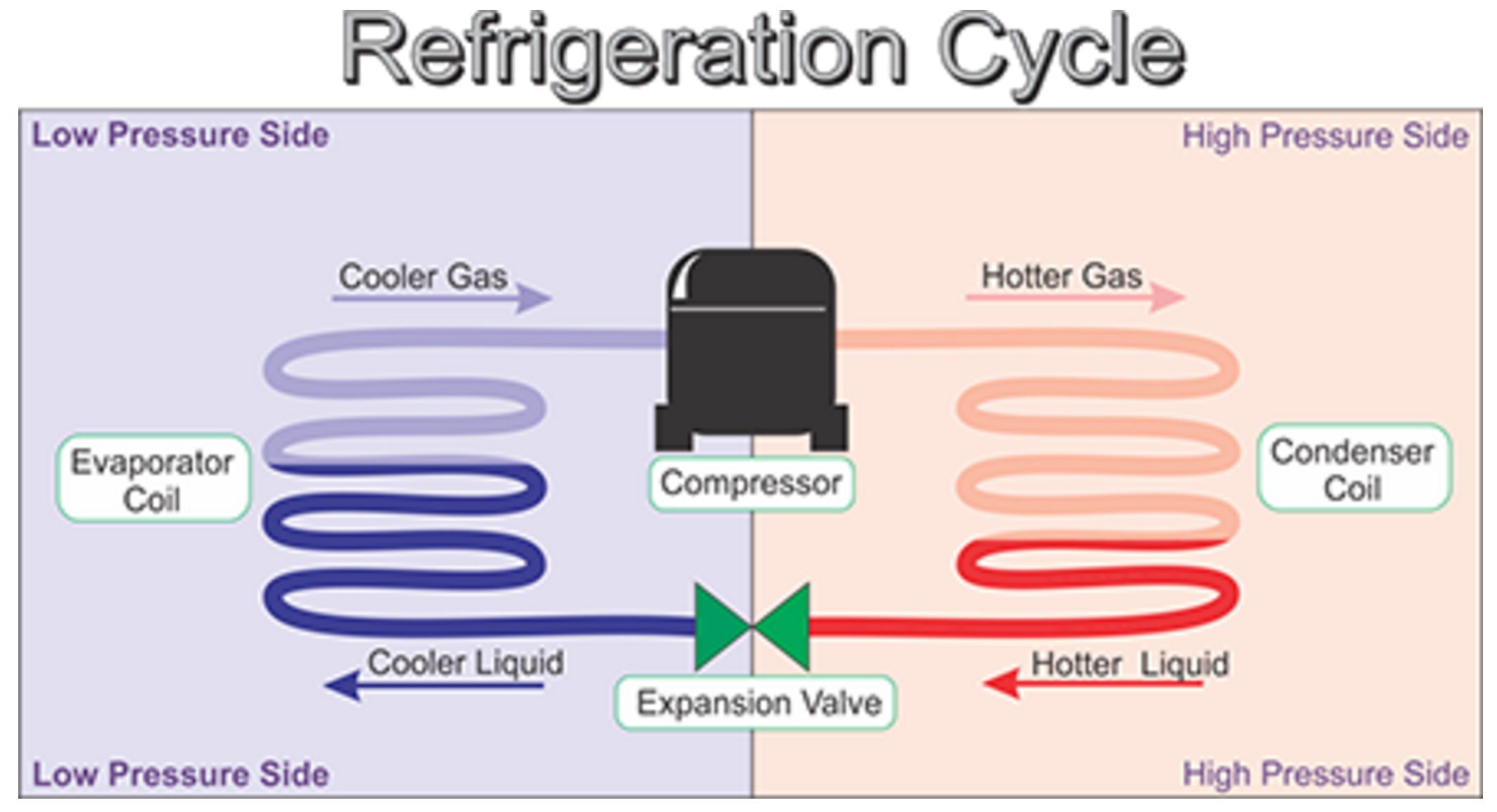
HVAC Refrigeration Cycle Diagram

refrigeration cycle Diagram Quizlet

Refrigeration cycle diagram explained Refrigeration HVAC/R and
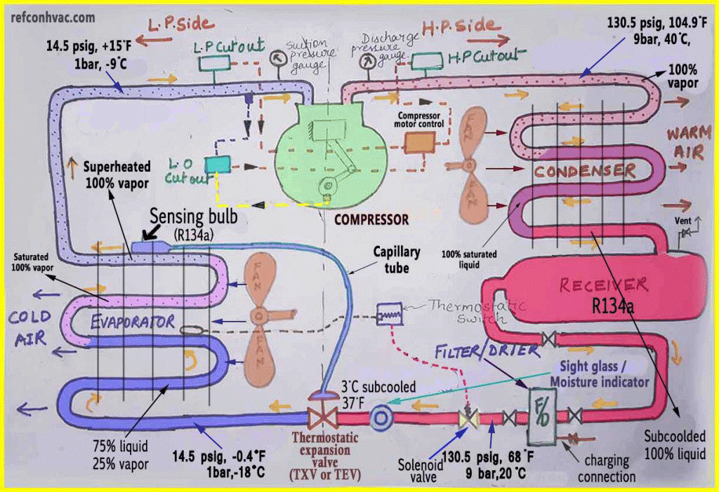
Refrigeration Cycle A Helpful Illustrated Guide Refcon hvac

The Refrigeration Cycle
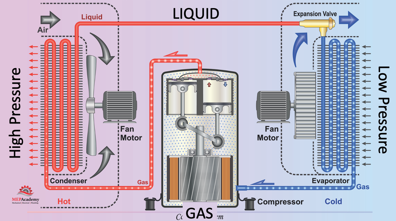
Refrigeration Cycle 101 MEP Academy
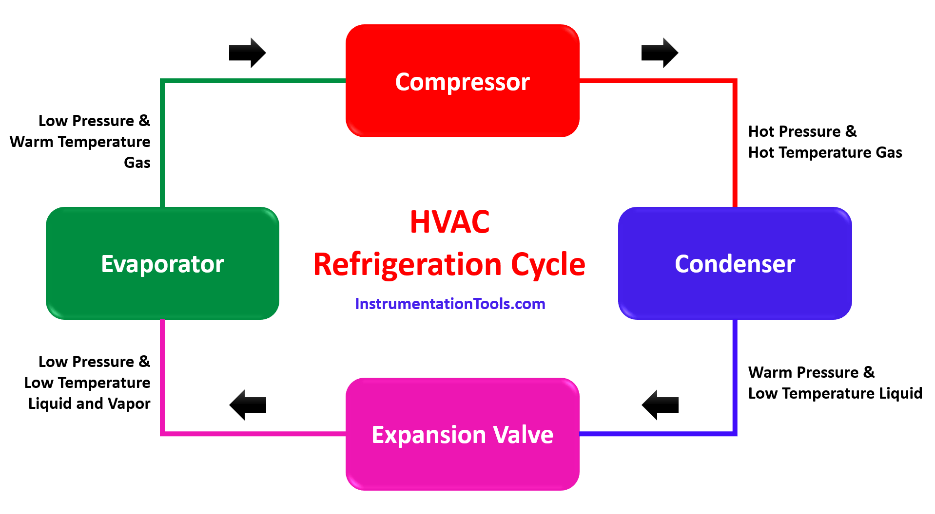
HVAC Refrigeration Cycle

How Does It Work? The Refrigeration Cycle

HVAC/R Refrigerant Cycle Basics HVAC School (2022)
The Liquid Region Represents The Refrigerant’s State During The Condensation Process, While The Boiling Region Represents The Refrigerant’s State During The Evaporation Process.
The Red Dots Inside The Piping Represent Discharge Vapor.
How It Works And What You Need To Know:
The Condenser Accepts The Gas From The Compressor And, Through Some Cooling Medium, Condenses It To A High Pressure, Cool Temperature Liquid.
Related Post: