Pressure Relief Valve Sizing Chart
Pressure Relief Valve Sizing Chart - Npt, flanged, male socket weld 0.074 to 0.503 in2 (47.74 to 324.5 mm2) connections: Information contained in this course applies to the overpressurization protection of pressure vessels, lines, and systems. ½” x 1 to 2 x 2 and 1½” x 2½” orifices: Correct and comprehensive pressure relief valve sizing is a complex multi. The user is responsible for correct determination of service conditions and the suitability of this program for a specific application. The specific design challenges and special factors specific to each installation of a relief device will affect the relief sizing estimates. Web emerson global | emerson Valve sizing software and tools. Overview of control valve sizing. Emerson can help you size and select the fisher control valve most appropriate for existing service conditions. The graphs cover most ordinary industrial applications—from the smallest metering valves to large ball valves, at system pressures up to 10 000 psig and 1000 bar. Should additional clarification be required, contact crosby. Web the calculation on this page is specifically for sizing. 0.074 to 0.503 in2 (47.74 to 324.5 mm2) connections: Web the calculation on this page is specifically for sizing and flow rate determination for rupture disks, spring pressure relief valves, and pilot operated pressure relief valves, or valves that have a rupture disk in combination with a spring. The user is responsible for correct determination of service conditions and the. Overview of control valve sizing. Possible valve damage, impaired performance, undersized discharge piping and effluent handling systems, and higher costs. There is no effect on the capacity and function up to a pressure loss of 3%. Web pressure relief valve orifice area and maximum available flow. Web two common standards used for the sizing of pressure relief valves are iso. Web valve sizing calculations (traditional method) introduction. The user is responsible for correct determination of service conditions and the suitability of this program for a specific application. Web properly sized relief valves will provide the required protection, while also avoiding issues with excessive flow rates, including: Web finding the necessary relief area for the relief device is the aim of. Web valve sizing calculations (traditional method) introduction. Web pressure relief valve orifice area and maximum available flow. There is no effect on the capacity and function up to a pressure loss of 3%. Web properly sized relief valves will provide the required protection, while also avoiding issues with excessive flow rates, including: ½” x 1 to 2 x 2 and. 0.074 to 0.503 in2 (47.74 to 324.5 mm2) connections: Web valve sizing calculations (traditional method) introduction. The graphs cover most ordinary industrial applications—from the smallest metering valves to large ball valves, at system pressures up to 10 000 psig and 1000 bar. Please consult the appropriate product catalog for specific data. Web two common standards used for the sizing of. Web valve sizing calculations (traditional method) introduction. The latter standard is the most widely used for relief valve sizing. There is no effect on the capacity and function up to a pressure loss of 3%. Information contained in this course applies to the overpressurization protection of pressure vessels, lines, and systems. Overview of control valve sizing. ½” x 1 to 2 x 2 and 1½” x 2½” orifices: Please consult the appropriate product catalog for specific data. Information contained in this course applies to the overpressurization protection of pressure vessels, lines, and systems. The specific design challenges and special factors specific to each installation of a relief device will affect the relief sizing estimates. This sizing. Web it is traditional to size and select pressure relief valves specified per api rp 526 for gas, vapor and steam applications using the api rp 520 kd value of 0.975 and the effective areas of api rp 526. Web understanding of relief valve sizing calculations. The specific design challenges and special factors specific to each installation of a relief. The latter standard is the most widely used for relief valve sizing. Web two common standards used for the sizing of pressure relief valves are iso 4126 & american petroleum institute api rp520 part i. Correct and comprehensive pressure relief valve sizing is a complex multi. Please consult the appropriate product catalog for specific data. + asme does not certify. Web the calculation on this page is specifically for sizing and flow rate determination for rupture disks, spring pressure relief valves, and pilot operated pressure relief valves, or valves that have a rupture disk in combination with a spring. Valve sizing software and tools. Web valve sizing calculations (traditional method) introduction. Valve types and their applications. Please consult the appropriate product catalog for specific data. Web properly sized relief valves will provide the required protection, while also avoiding issues with excessive flow rates, including: There are now standardized calculations that are becoming accepted worldwide. Pressure losses >3% must be taken into account in the capacity calculation. Possible valve damage, impaired performance, undersized discharge piping and effluent handling systems, and higher costs. The specific design challenges and special factors specific to each installation of a relief device will affect the relief sizing estimates. Overview of control valve sizing. ½” x 1 to 2 x 2 and 1½” x 2½” orifices: Should additional clarification be required, contact crosby. Web too often pressure relief valve sizes are determined by merely matching the size of an existing available vessel nozzle, or the size of an existing pipe line connection. Trbs is not yet available for specification of the safety valve. Web finding the necessary relief area for the relief device is the aim of the relief sizing calculation.
Relief Valve Size Calculation Size Chart ASME Requirements
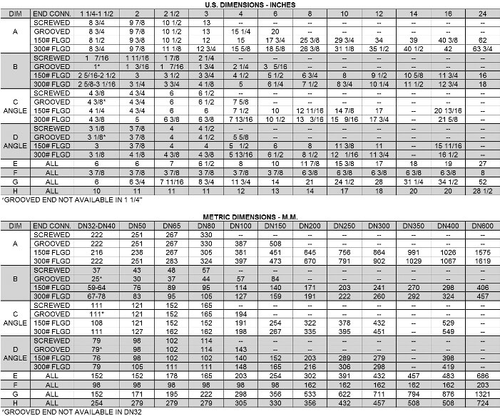
Series 108 Pressure Relief Valves OCV

Air Release Valve Sizing Chart How To Choose The Right Valve

Relief Valve Size Calculation Size Chart ASME Requirements
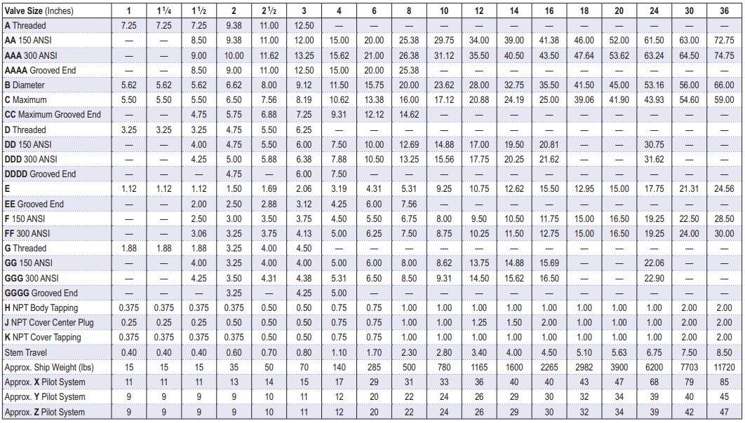
Pressure Relief Valve Piping System Indonesia
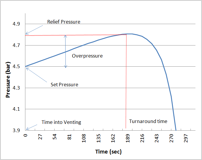
Psv Relief Sizing bluepase
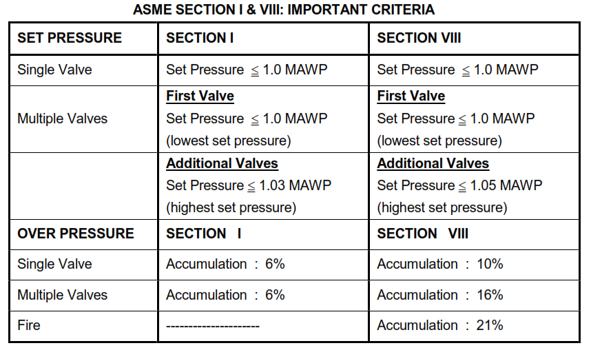
Relief Valves Sizing, Design, Purchase, Testing, Inspection and

Relief Valves for Centrifugal Pumps According to NFPA 20 Fire
PRESSURE RELIEF VALVES

Relief Valve Size Calculation Size Chart ASME Requirements
There Is No Effect On The Capacity And Function Up To A Pressure Loss Of 3%.
Information Contained In This Course Applies To The Overpressurization Protection Of Pressure Vessels, Lines, And Systems.
Npt, Flanged, Male Socket Weld
This Sizing Program Is A Powerful Tool, Yet Easy To Use.
Related Post: