Pneumatic Symbols Chart
Pneumatic Symbols Chart - Symbols show the methods of actuation, the number of positions, the flow paths and the number of ports. Every symbol has three parts (see figuretoright). How do i select a pneumatic symbol? Every valve symbol has multiple parts (see figure below). These symbols represent different elements used to control air flow in the system, such as directional control valves, pressure control valves, flow control valves, etc. Web the chart above shows a good representation of common symbols and more is outlined below. Graphic symbols for fluid power systems Here is a brief breakdown of how to read a symbol: Volume symbol description circuit symbols are used through this catalogue and on the labels of most smc pneumatic products. Web these valves provide awealth of information about the valve it represents. Every valve symbol has multiple parts (see figure below). Web schematic symbols are used to identify and graphically depict the function of fluid power components. Volume symbol description circuit symbols are used through this catalogue and on the labels of most smc pneumatic products. Learn how to read and interpret pneumatic circuit symbols for valves, actuators and other components. Schematic. Web composite symbols can be devised for any fluid power component by combining basic symbols. Symbols show the methods of actuation, the number of positions, the flow paths and the number of ports. At the desired cycle rate and using 1/4” od tubing (0.156” id), pressure losses in the tubing are about 1.5 psi per foot. For port identification and. In this lesson we'll take a look at the schematic symbols for common pneumatic components including but not limited to source elements like motor prime. Web pneumatic schematic symbols are graphical representations used to represent components and operations in pneumatic systems. There are several symbol systems and conventions in use around the world, most officially recognised by standards bodies. Web. 1.2.1.6 this standard provides basic symbols, which differentiate between hydraulic and pneumatic fluid power media. A practical guide to pneumatics is a good place to There are several symbol systems and conventions in use around the world, most officially recognised by standards bodies. All pneumatic circuits consist of valves. Web graphic symbols for pneumatic equipment. Web composite symbols can be devised for any fluid power component by combining basic symbols. Schematic drawings document the machine logic only and are never to be used as a piping diagram. To posltlon quick exhaust shuttle symbol description solenoid internal pilot supply reuote pilot supply md lot n and pilot or manual override pilot lines and functions description. Web. At the desired cycle rate and using 1/4” od tubing (0.156” id), pressure losses in the tubing are about 1.5 psi per foot. Every valve symbol has multiple parts (see figure below). 1.2.1.6 this standard provides basic symbols, which differentiate between hydraulic and pneumatic fluid power media. Simplified symbols are shown for commonly used components. How do i select a. Using a 2” bore cylinder, about 64 psi is required to move the load. These symbols represent different elements used to control air flow in the system, such as directional control valves, pressure control valves, flow control valves, etc. For port identification and operator marking see iso 9461 (hydraulic) or bs iso 5599 (pneumatic). Some commonly used symbols include directional. All pneumatic circuits consist of valves. Simplified symbols are shown for commonly used components. Symbols show the methods of actuation, the number of positions, the flow paths and the number of ports. Web graphic symbols for pneumatic equipment. Web these valves provide awealth of information about the valve it represents. How do i select a pneumatic symbol? These symbols represent different elements used to control air flow in the system, such as directional control valves, pressure control valves, flow control valves, etc. 1.2.1.6 this standard provides basic symbols, which differentiate between hydraulic and pneumatic fluid power media. Learn how to read and interpret pneumatic circuit symbols for valves, actuators and. See examples, definitions and interactive diagrams of common pneumatic devices. Using a 2” bore cylinder, about 64 psi is required to move the load. Learn how to read and interpret pneumatic circuit symbols for valves, actuators and other components. Web the chart above shows a good representation of common symbols and more is outlined below. There are several symbol systems. Simplified symbols are shown for commonly used components. See examples, definitions and interactive diagrams of common pneumatic devices. Web the chart above shows a good representation of common symbols and more is outlined below. There are several symbol systems and conventions in use around the world, most officially recognised by standards bodies. Take a look at our comprehensive list of common symbols for use in circuit diagrams, available to download in pdf format. How do i select a pneumatic symbol? Schematic drawings document the machine logic only and are never to be used as a piping diagram. Learn how to read and interpret pneumatic circuit symbols for valves, actuators and other components. Web symbols representing these valves provide a wealth of information about the valve they represent. Web find and download pneumatic symbols in.dxf format for your circuit design. Web the chart above shows a good representation of common symbols and more is outlined below. 1.2.1.6 this standard provides basic symbols, which differentiate between hydraulic and pneumatic fluid power media. Web pneumatic symbols for system diagrams and component identification contents z z z z z z z z standards b i symbols basic b l functional elements flowlines connections conditioners and plant pressure regulators relief valves z z z z z z z z actuators v l symbol valve b l structure t t valve functions three position valves operators port. Web graphic symbols for pneumatic equipment. Here is a brief breakdown of how to read a symbol: Hereisabrief breakdown of how to read asymbol:
Pneumatic Symbols Chart With Meanings
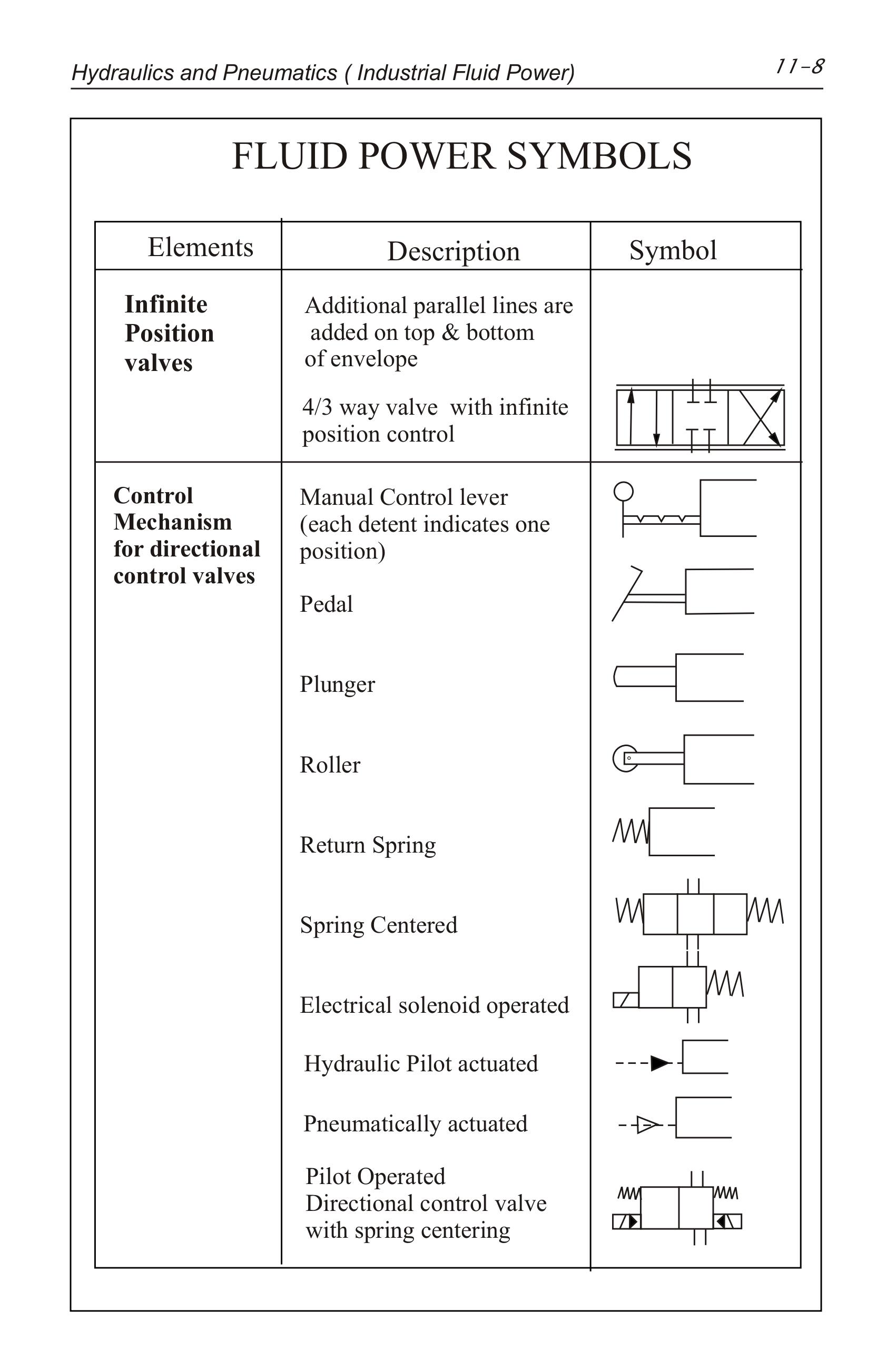
Hydraulics Pneumatics Symbols

Pneumatic Symbols
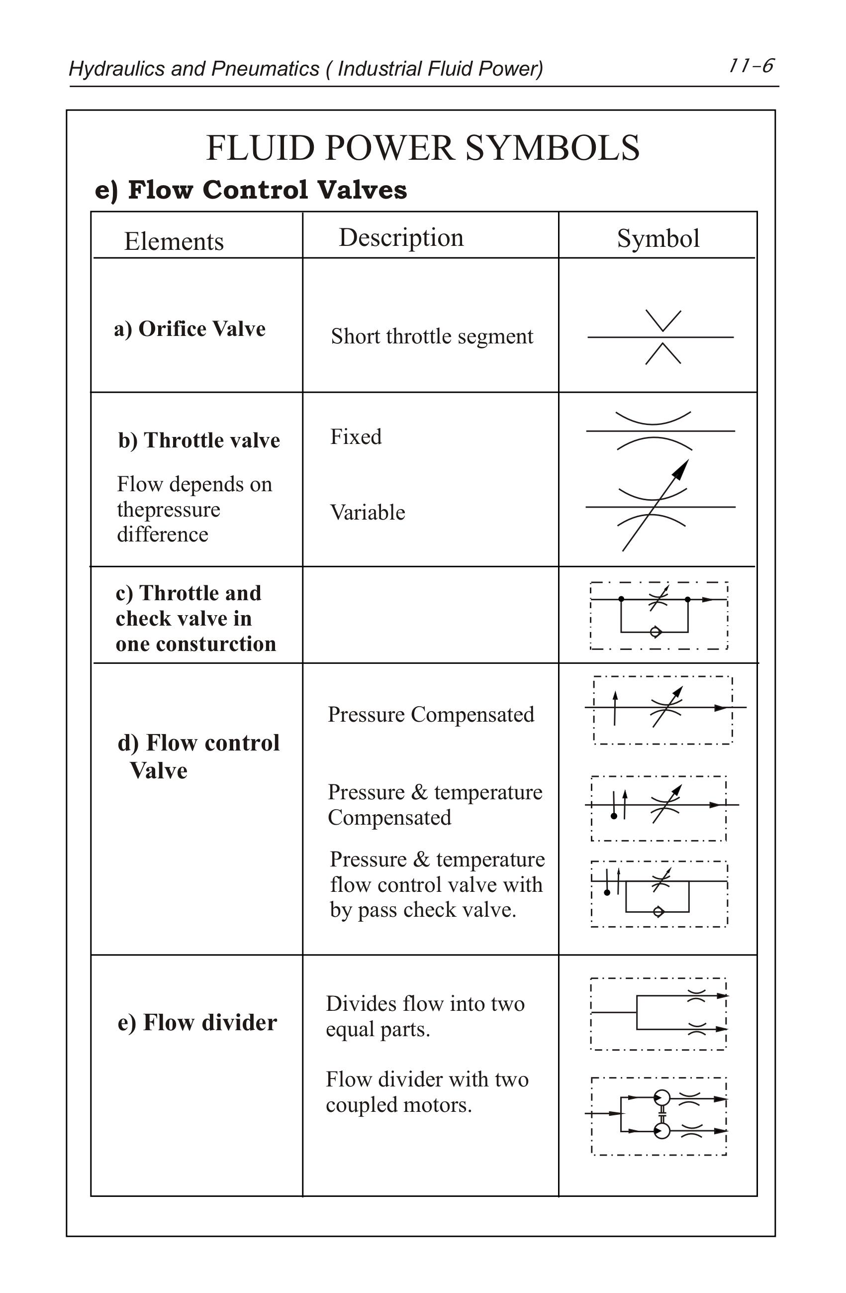
Pneumatic Symbols Chart With Meanings
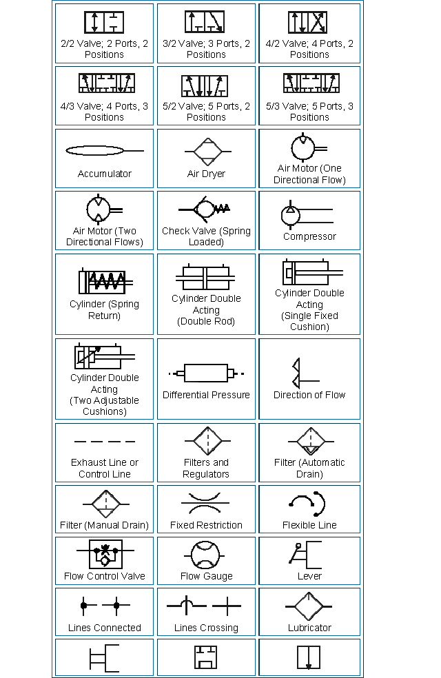
Pneumatics Banff Academy Technological Studies 07

Pneumatic Circuit Diagram Symbols

Pneumatic Symbols explained Pneumatics & Sensors Ireland
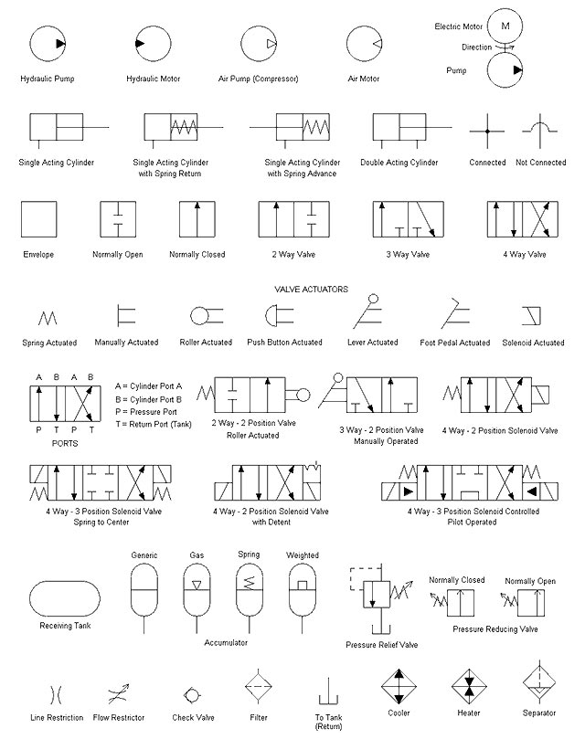
Pneumatic Valve Symbols Explained
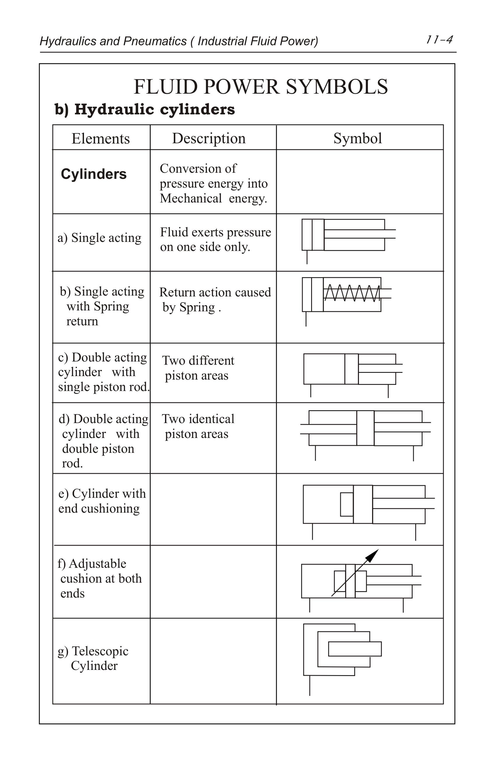
Hydraulics Pneumatics Symbols
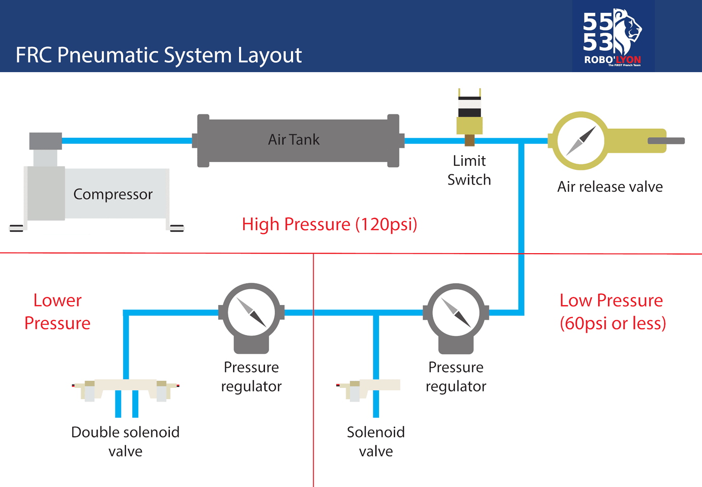
Pneumatic Symbols And Functions
A Practical Guide To Pneumatics Is A Good Place To
To Posltlon Quick Exhaust Shuttle Symbol Description Solenoid Internal Pilot Supply Reuote Pilot Supply Md Lot N And Pilot Or Manual Override Pilot Lines And Functions Description.
Every Valve Symbol Has Multiple Parts (See Figure Below).
Web Pneumatic Schematic Symbols Are Graphical Representations Used To Represent Components And Operations In Pneumatic Systems.
Related Post: