Plan View Drawing
Plan View Drawing - Certain fundamentals characterise and define a plan view drawing: Typical scales are 1:100 for site plans and 1:50 for architectural floor plans. The width dimension is common to the front and top views. The plan view is the most common floor drawing in interior design. All architecture drawings are drawn to a scale and as described here in great detail, there are set scales that should be used depending on which drawing is being produced, some of which are below: There are three types of pictorial views: Plans are drawn to scale, with all features and components represented smaller than the actual size. Web engineering drawing basics explained. Web a floor plan (or floor drawing) is an orthographic plan view (or top view) looking down on the various floor levels. Each one of these views shows two of the principle The elevation view is the view from one side of the object. Web a floor plan (or floor drawing) is an orthographic plan view (or top view) looking down on the various floor levels. The plan view is a map of the project area with background imagery, annotations, and the linear project feature. Floor plans identify rooms by name or. Engineering drawings use standardised language and symbols. An engineering drawing is a subcategory of technical drawings. The profile view is an xy plot, typically used to represent the existing elevation of the project feature. The top view may be termed the plan. Floor plans identify rooms by name or number. The profile view is an xy plot, typically used to represent the existing elevation of the project feature. Web the most common plan view drawing is a floor plan, but there are also reflected ceiling plans, details plan view, etc. The purpose is to convey all the information necessary for manufacturing a product or a part. Web a primer on. If desired, the rear view may be shown both ways. The elevation view is the view from one side of the object. And side views are sometimes called elevations, e.g., front elevation. The top view may be termed the plan. We get a bird’s eye perspective of the home’s interior, including room layout with clearly marked entrances, windows, furniture, partitions,. An engineering drawing is a subcategory of technical drawings. Web a primer on what these various views are and how to draw them. The two main types of views (or “projections”) used in drawings are: The width dimension is common to the front and top views. Floor plans identify rooms by name or number. Engineering drawings use standardised language and symbols. The plan view is the most common floor drawing in interior design. If desired, the rear view may be shown both ways. And side views are sometimes called elevations, e.g., front elevation. The width dimension is common to the front and top views. The plan view is a map of the project area with background imagery, annotations, and the linear project feature. All architecture drawings are drawn to a scale and as described here in great detail, there are set scales that should be used depending on which drawing is being produced, some of which are below: Floor plans identify rooms by name. The plan view is the most common floor drawing in interior design. Web a primer on what these various views are and how to draw them. Web key features of plan view. There are three types of pictorial views: The plan view is a map of the project area with background imagery, annotations, and the linear project feature. Web types of views used in drawings. And side views are sometimes called elevations, e.g., front elevation. Web architecture drawing scales. All architecture drawings are drawn to a scale and as described here in great detail, there are set scales that should be used depending on which drawing is being produced, some of which are below: Certain fundamentals characterise and. The width dimension is common to the front and top views. Engineering drawings use standardised language and symbols. Floor plans are one of the most important drawings for construction, as they provide the most information about the building. The top view may be termed the plan. Web engineering drawing basics explained. The purpose is to convey all the information necessary for manufacturing a product or a part. There are three types of pictorial views: Plans are drawn to scale, with all features and components represented smaller than the actual size. The width dimension is common to the front and top views. Web a floor plan (or floor drawing) is an orthographic plan view (or top view) looking down on the various floor levels. Each one of these views shows two of the principle The elevation view is the view from one side of the object. Web the most common plan view drawing is a floor plan, but there are also reflected ceiling plans, details plan view, etc. If desired, the rear view may be shown both ways. Floor plans identify rooms by name or number. Web key features of plan view. Typical scales are 1:100 for site plans and 1:50 for architectural floor plans. Web architecture drawing scales. We get a bird’s eye perspective of the home’s interior, including room layout with clearly marked entrances, windows, furniture, partitions, etc. The plan view is a map of the project area with background imagery, annotations, and the linear project feature. This makes understanding the drawings simple with little to no personal.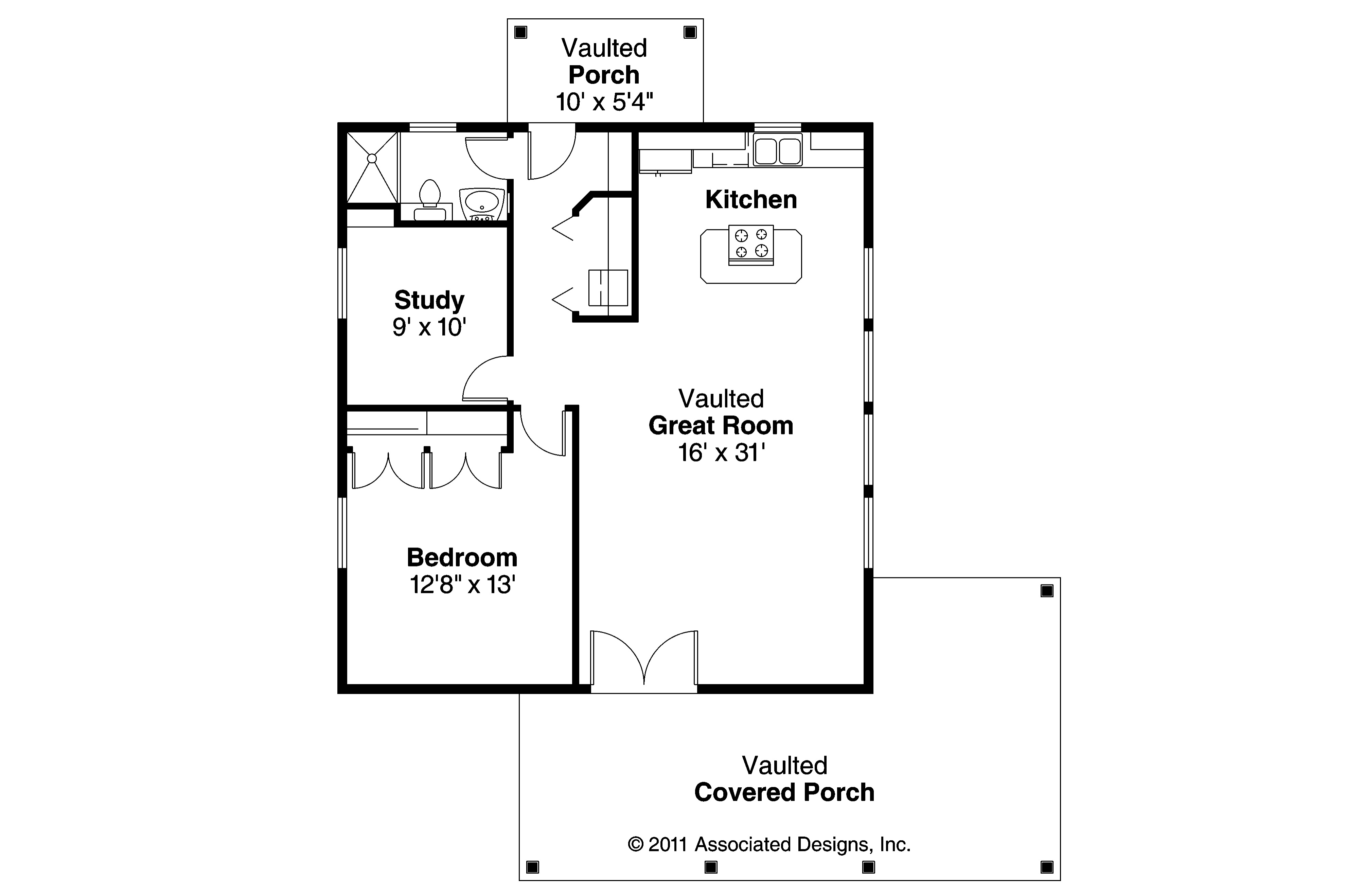
51+ Simple House Plan And Elevation Drawings
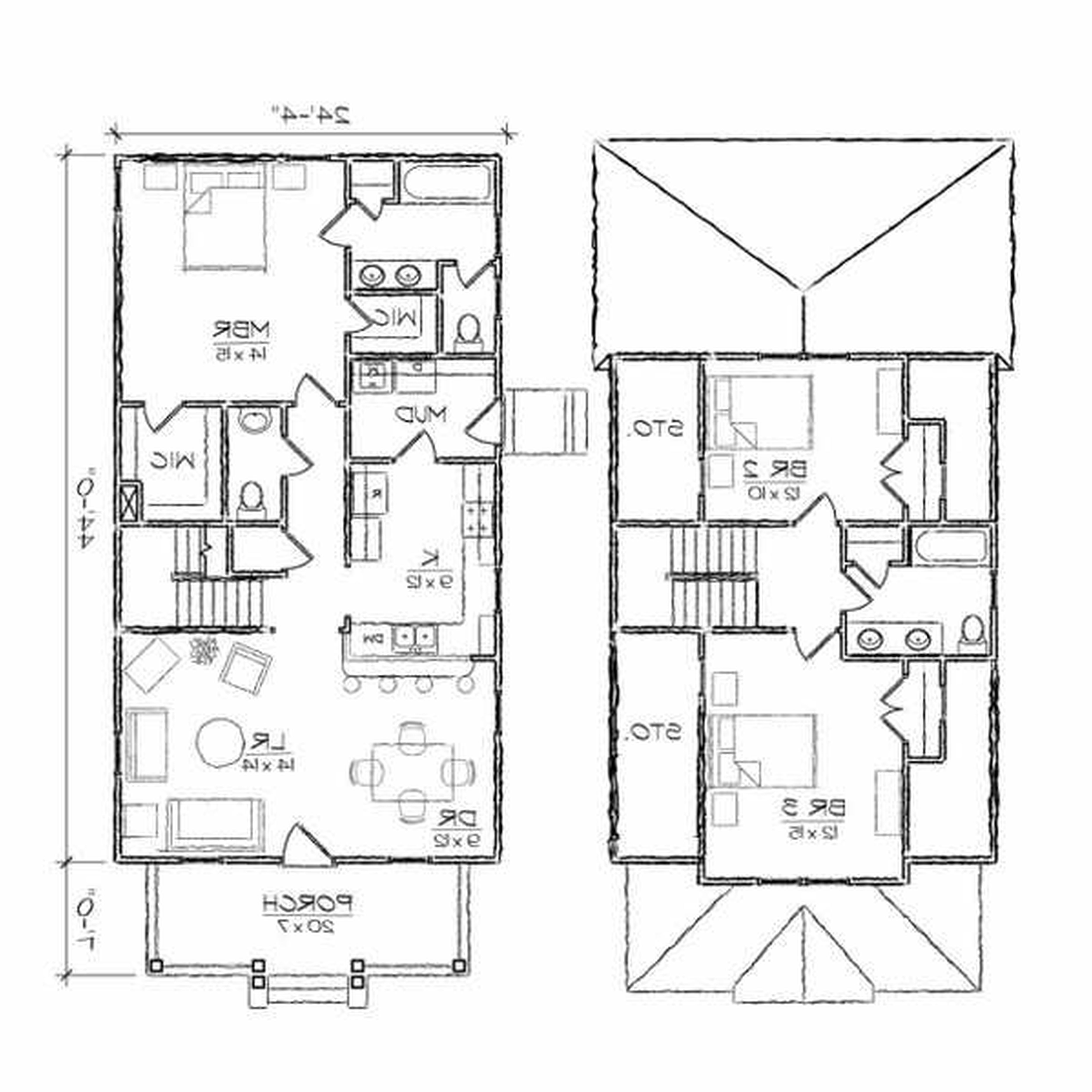
House Site Plan Drawing at GetDrawings Free download
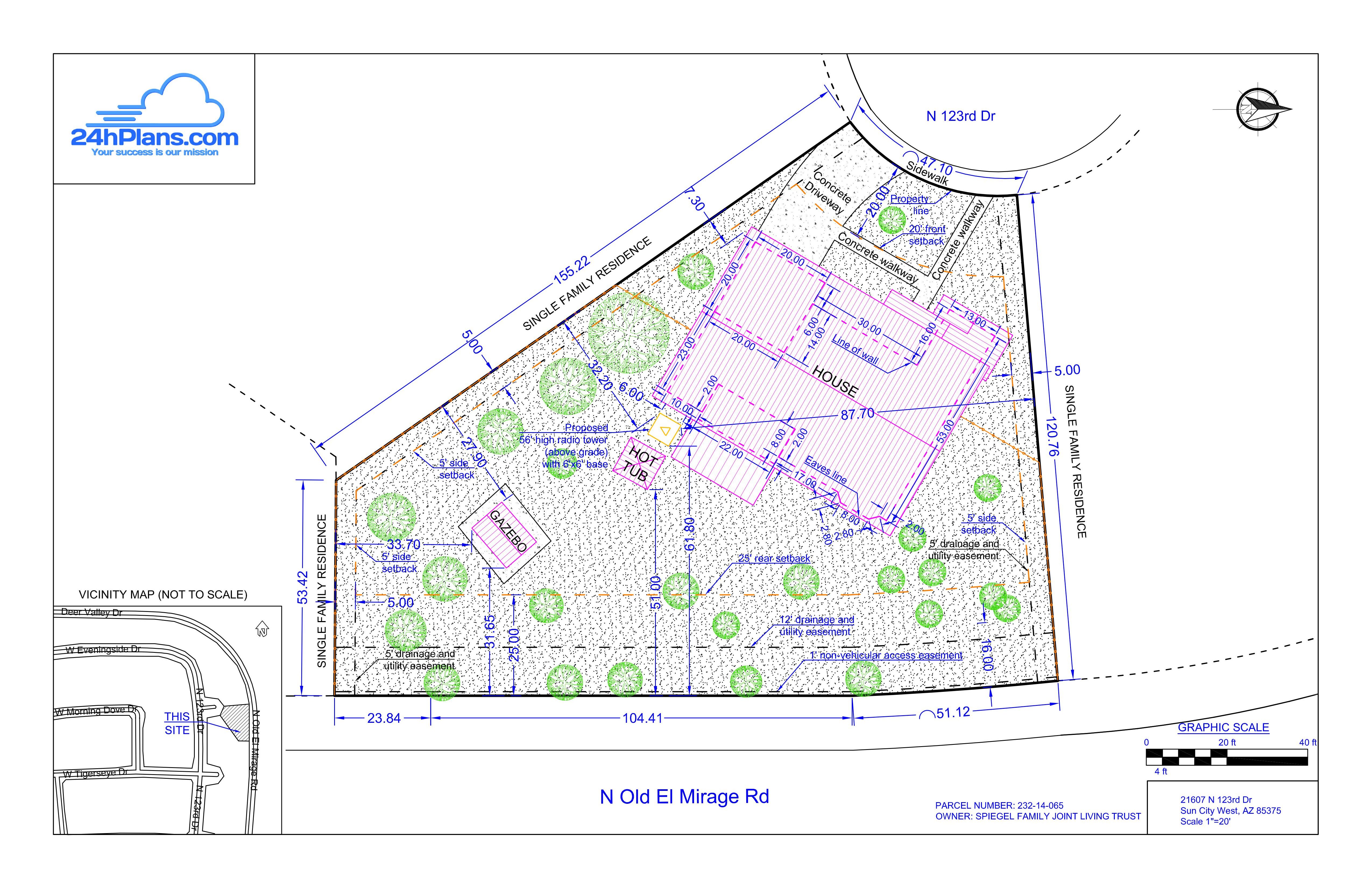
The Ultimate Site Plan Guide for Residential Construction Plot Plans
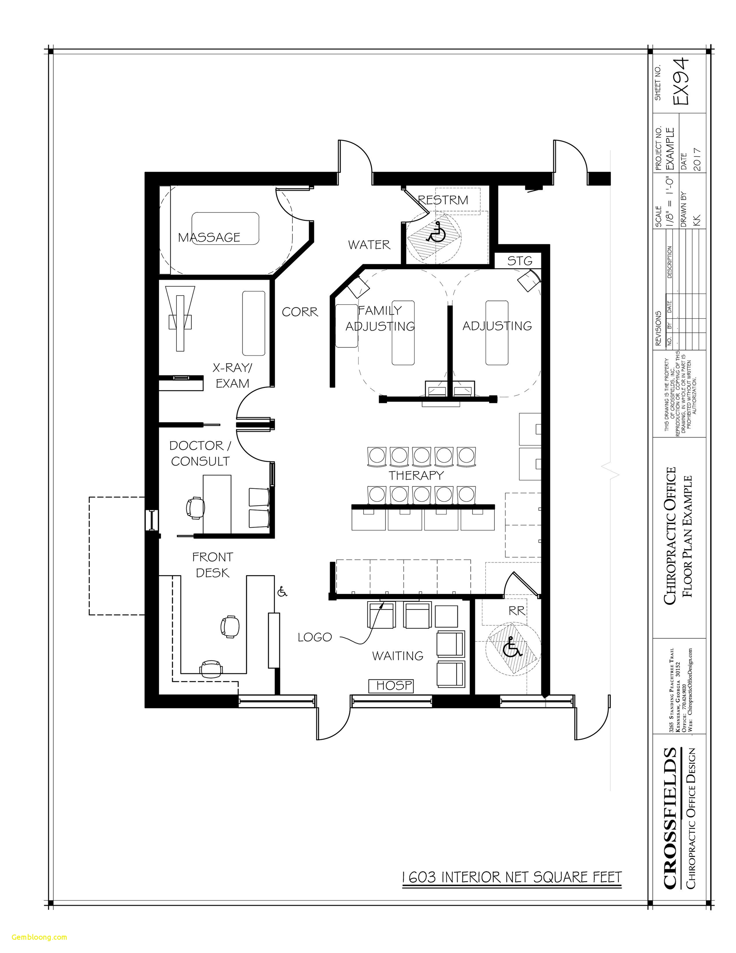
Building Drawing Plan Elevation Section Pdf at

Plan Elevation Section Drawing at GetDrawings Free download

How To Draw A Floor Plan Like A Pro The Ultimate Guide The Interior
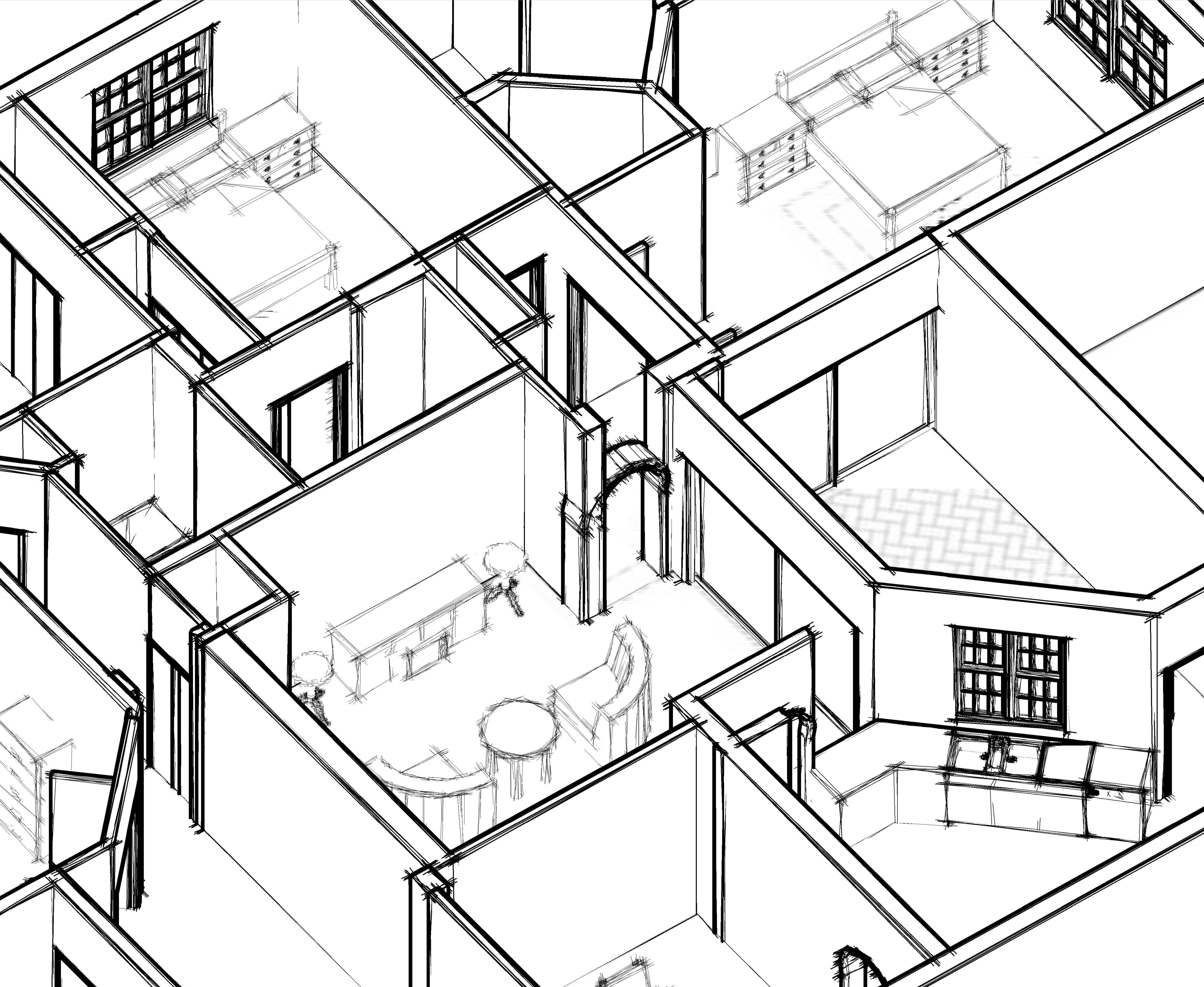
Building Drawing Plan Elevation Section Pdf at GetDrawings Free download

House Elevation Drawing Planning Drawings JHMRad 21734
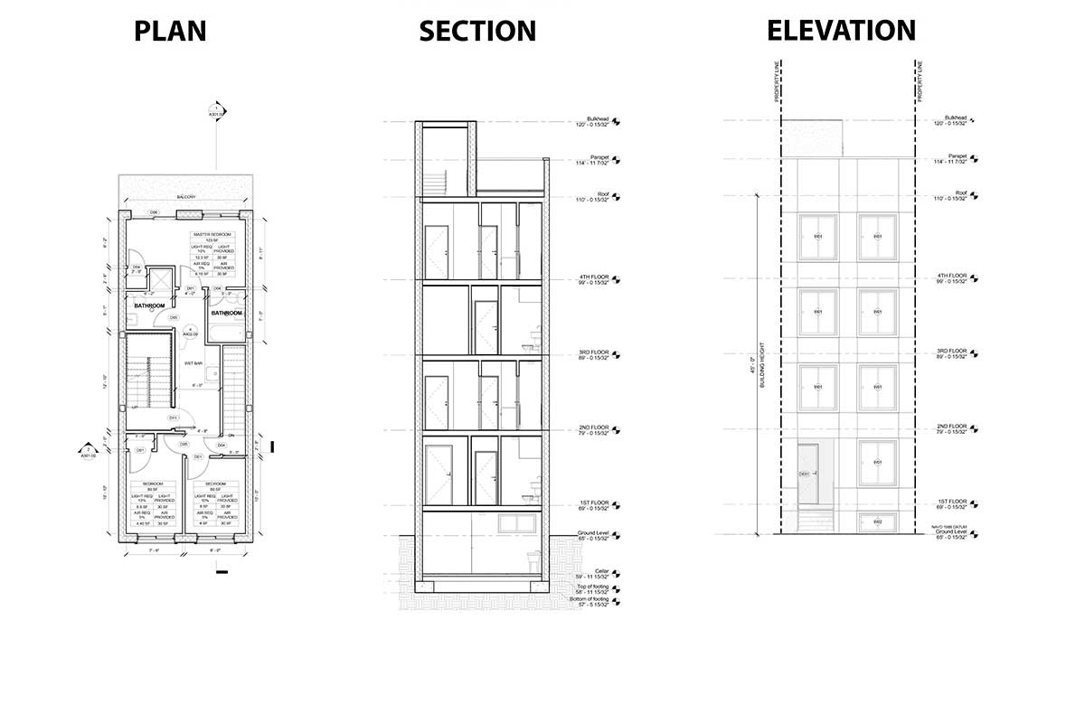
Plan, Section, Elevation Architectural Drawings Explained · Fontan

Building Drawing Plan Elevation Section Pdf at GetDrawings Free download
Web A Primer On What These Various Views Are And How To Draw Them.
Engineering Drawings Use Standardised Language And Symbols.
Floor Plans Are One Of The Most Important Drawings For Construction, As They Provide The Most Information About The Building.
An Engineering Drawing Is A Subcategory Of Technical Drawings.
Related Post: