Pid Drawing
Pid Drawing - In the process industry, a standard set of symbols is used to prepare drawings of processes. Web different software is available to create or draw a p&id diagram. The symbology for the identification of the measurement and control instrumentation on the flow and process diagrams and on the p&id (piping & instrument diagram), commonly called p&i (piping & instrumentation), is generally compliant with the standard isa (instrumentation society of automation) identified as. It serves as a vital tool in the process industry, forming the backbone of the design phase and providing a detailed layout of the plant's process. On the drawing page, select the shape to which you would like to add data. Select, copy and paste the components you want to use. If this tank were to fill, materials would get clogged up in the reactor. Therefore, if the tank reaches 90% of its total capacity. We live in an exciting time. Web p&id drawings 101. Web on the data tab, click shape data window. Web draw a proper p&id diagram of the following process: Web make your own p&id diagrams with this free online drawing tool. A storage tank is filled with condensed products formed via the cstr in example 1. Without a doubt, visual paradigm online is the best p&id software to create schematics. Web draw a proper p&id diagram of the following process: Select, copy and paste the components you want to use. Web on the data tab, click shape data window. Without a doubt, visual paradigm online is the best p&id software to create schematics for the process industry. Click in each shape data field, and type or select a value. Piping and instrumentation diagrams, or p&ids, are used to create important documentation for process industry facilities. To add the property set to shapes on a drawing, select the shapes. The tag number helps in identifying the device, whereas the line is the location indicator. Web in this video, you will learn the basics of piping and instrumentation diagrams (also called. P&ids are used to develop guidelines and standards for facility operation; The symbology for the identification of the measurement and control instrumentation on the flow and process diagrams and on the p&id (piping & instrument diagram), commonly called p&i (piping & instrumentation), is generally compliant with the standard isa (instrumentation society of automation) identified as. On the drawing page, select. Web here, i have tried to explain p&id and pefs in an easy way. It is the basic training document to explain the process details to operation guys, field engineers, and maintenance professionals. Web make your own p&id diagrams with this free online drawing tool. The instrument symbols used in these drawings are generally based on. P&id is a schematic. For example, a tank can be customized with various roof types, and users can toggle between hiding and showing the stump. You'll be surprised by its abundant symbols and templates, amazed at how easy it works and satified with its service and price. Only a few steps to follow to create a p&id diagram, but one who does it should. Edrawmax online helps designers and engineers to create p&id drawings fast and easy. Web on the data tab, click shape data window. We've broken them down into seven main groups: Piping and instrumentation diagrams, or p&ids, are used to create important documentation for process industry facilities. More fully developed piping and instrumentation diagrams (p&ids) are shown in a p&id. Create the full list of instruments and equipment required for the process. All the below p&id symbols are existing in the symbol library of edraw max. Since p&ids are graphic representations of processes, they have some inherent limitations. Web p&id drawings 101. Do one of the following: The shapes in this legend are representative of the functional relationship between piping, instrumentation, and system equipment units. More fully developed piping and instrumentation diagrams (p&ids) are shown in a p&id. All the below p&id symbols are existing in the symbol library of edraw max. Web p&id drawings 101. Select, copy and paste the components you want to use. The instrument symbols used in these drawings are generally based on. Web on the data tab, click shape data window. P&id symbols, which stand for piping and instrumentation diagram symbols, are graphical representations used in engineering and process industries to depict the process flow, equipment, instrumentation, and control systems of a system or a plant. Piping and instrumentation diagrams, or. We live in an exciting time. Because using simplified and united symbols and vivid equipment icons, people are more likely to know the p&id drawings and what they represent. More fully developed piping and instrumentation diagrams (p&ids) are shown in a p&id. Web p&id drawings 101. The tank contains a level controller at a set point on the top of the tank. No matter how intricate your process or system, lucidchart can help you build, style, edit, and share your diagram as you please. Customize existing components and make new ones. The symbology for the identification of the measurement and control instrumentation on the flow and process diagrams and on the p&id (piping & instrument diagram), commonly called p&i (piping & instrumentation), is generally compliant with the standard isa (instrumentation society of automation) identified as. In the process industry, a standard set of symbols is used to prepare drawings of processes. The instrument symbols used in these drawings are generally based on. Without a doubt, visual paradigm online is the best p&id software to create schematics for the process industry. On the drawing page, select the shape to which you would like to add data. It serves as a vital tool in the process industry, forming the backbone of the design phase and providing a detailed layout of the plant's process. P&id symbols, which stand for piping and instrumentation diagram symbols, are graphical representations used in engineering and process industries to depict the process flow, equipment, instrumentation, and control systems of a system or a plant. A storage tank is filled with condensed products formed via the cstr in example 1. Web all the instruments in a p&id are marked by a circle with an assigned tag number and line inside.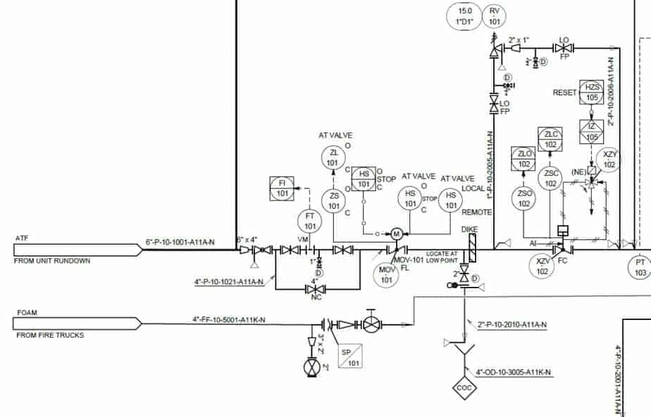
Learn How to Read P&ID Drawings A Complete Guide (2023)
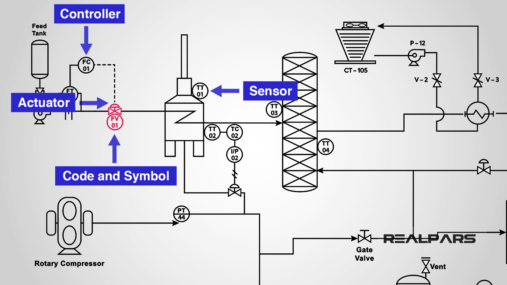
P&ID Valve Symbols How to read them on most common control valves
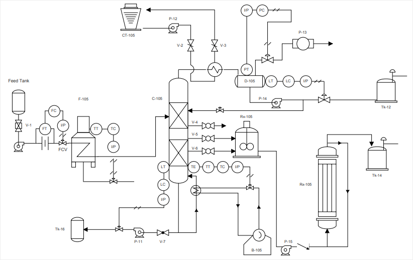
How to Read a P&ID Drawing Quickly and Easily Edraw Max

How to Read and Interpret Piping and Instrumentation Diagrams (P&ID
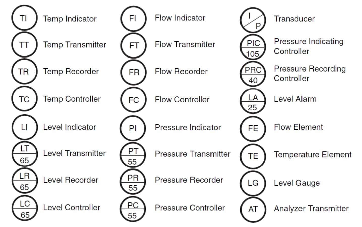
P&ID Symbol Diagram Basics Functional Identification and Naming
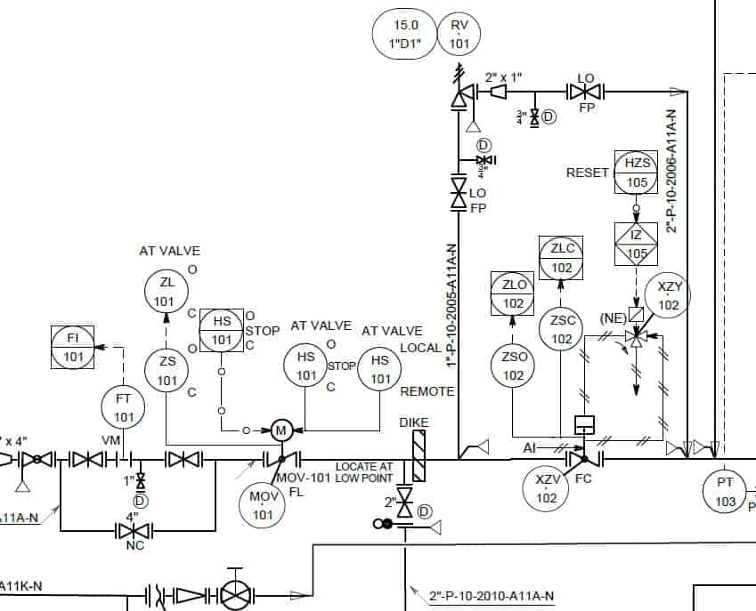
Learn How to Read P&ID Drawings A Complete Guide (2023)

How to Read P&ID Drawing A Complete Tutorial YouTube

P&ID Drawings 101 Corso Systems
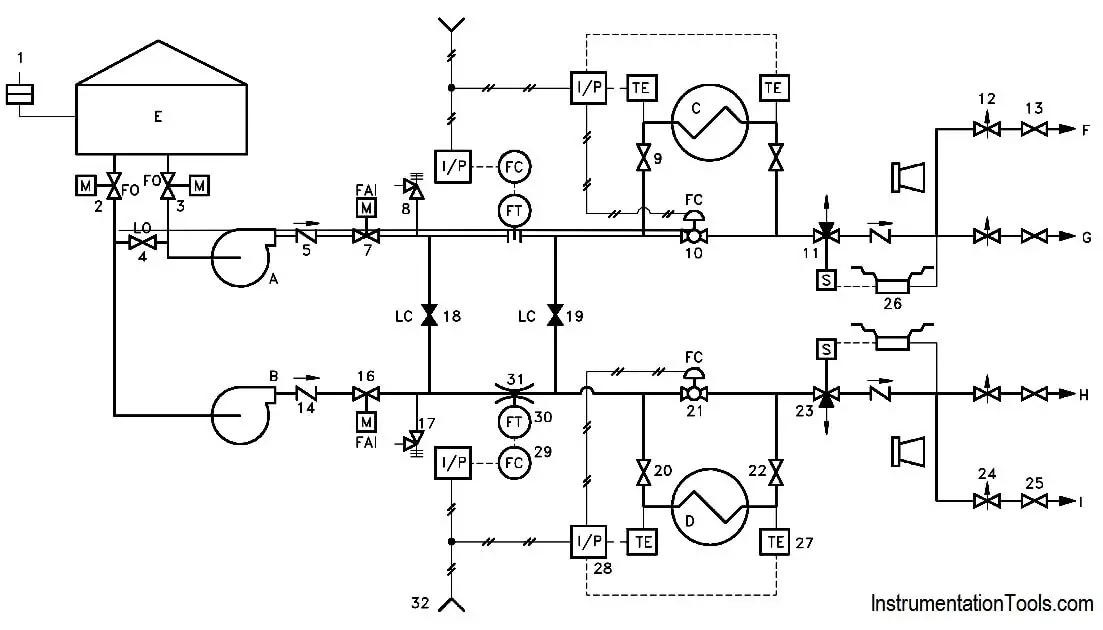
Piping and Instrumentation Documents Instrumentation Tools

P & ID Diagram. How To Read P&ID Drawing Easily. Piping
Only A Few Steps To Follow To Create A P&Id Diagram, But One Who Does It Should Know Well Knowledge About The Plant Process.
Web Here, I Have Tried To Explain P&Id And Pefs In An Easy Way.
Piping And Instrumentation Diagrams, Or P&Ids, Are Used To Create Important Documentation For Process Industry Facilities.
P&Id Is A Schematic Drawing That Gives A Primary Visual Representation Of A Process Control System.
Related Post: