Oil Burner Electrode Adjustment Chart
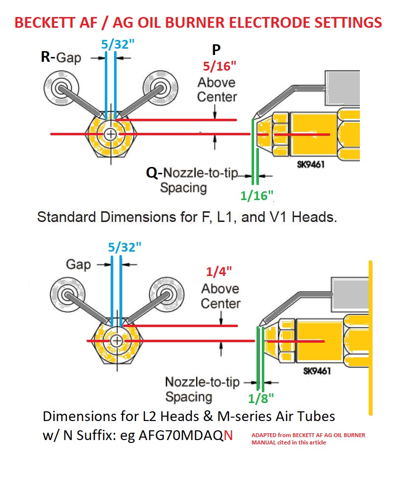
Oil Burner Electrode Adjustment Chart - Please review the comparison chart below: Move the escutcheon plate 1/16’’ forward for an afii burner with the fbx airtube combination. Web here we explain how to select & install an oil burner nozzle, we describe different oil burner nozzle firing rates & spray patterns; Web oil burner electrode settings guide & measurements: These burners may appear to be basically identical, but there are differences in design and performance. Whether you are installing a new burner, solving a problem, or conducting an annual service call, you eventually get to the point where you have to adjust the burner. (1) use wet pac ceramic liner to line the inside of chamber, (2) adjust burner (see finaladjustments column). An oil burner adjustment template provided by beckett corporation and shown just below summarizes the adjustment of the ignition electrodes & their positioning for beckett oil burners. Web the service technician’s guide to oem residential oil burner specifications. Set the electrode tip gap spacing (5/32”) by adjusting the tips to meet the two outside marks. Make sure you turn off the system, and be careful because you are working around fuel oil. The slightly negative pull overfire removes combustion products from the chamber and out the flue. Web f, fbx, l and v head settings are set by aligning the electrode tip with the 5/16″ cross marks. Please review the comparison chart below: Oil burner. Attach air tube ( if not already installed ) • carefully check and realign electrode tips after replacing nozzle, The “z” dimension is now set. Make sure the retention head is securely against the stops in the retention ring when the check the electrode tip settings. Web remove the nlea and gauge. Fuel units and oil lines Make sure the retention head is securely against the stops in the retention ring when the check the electrode tip settings. These burners may appear to be basically identical, but there are differences in design and performance. Web f, fbx, l and v head settings are set by aligning the electrode tip with the 5/16″ cross marks. Web here we. For more details, refer to “ connect fuel lines ” on page 7. If the condition still appears unsafe, contact the fire department. Please review the comparison chart below: Web remove the nlea and gauge. The stack dra, measured near the appliance flue connection, should be slightly higher than the overfire reading in most cases. Web oil burner electrode settings guide & measurements: The “z” dimension is now set. Web the beckett nx oil burner uses standard components, combines air and head settings into one adjustment and allows the zero position to be set. Fuel units and oil lines Adjust the escutcheon plate to the mark on the housing. Web adjusting electrodes in your oil burner is something normally done by a professional, however it is not rocket science. Web • verify that the burner fuel unit is compatible with the oil supply system. Make sure you turn off the system, and be careful because you are working around fuel oil. Web the service technician’s guide to oem residential. Make sure the retention head is securely against the stops in the retention ring when the check the electrode tip settings. Attach air tube ( if not already installed ) • carefully check and realign electrode tips after replacing nozzle, Burner with ce marking in conformity with eec directives: Web view and download riello 40 f10 installation & operating manual. Web oil burner electrode settings guide & measurements: Web the following diagram will show you the 5/16” standard specifications: The standard 5/16” dimension can be used on all series af, afg, sr, sm and sf burners using the “f” style head and will remain the standard setting for. Attach air tube ( if not already installed ) • carefully check. Web oil burner electrode settings guide & measurements: Specific applications may require testing more than one nozzle to obtain both clean combustion and a good. Web the following diagram will show you the 5/16” standard specifications: Web critical that all oil fired heating equipment be installed using combustion efficiency test equipment and the burners be set to the appliance manufacturers. The standard cautionary notes apply: Web this video shows you how to adjust the electodes in an oil burner and how to replace an oil nozzle. These burners may appear to be basically identical, but there are differences in design and performance. Web view and download riello 40 f10 installation & operating manual online. Web oil burner electrode settings guide. Make sure the retention head is securely against the stops in the retention ring when the check the electrode tip settings. If the homeowner is capable of doing most home repairs, he/she can adjust electrodes. Set the electrode tip gap spacing (5/32”) by adjusting the tips to meet the two outside marks. Burner with ce marking in conformity with eec directives: Adjust the escutcheon plate to the mark on the housing. (1) use wet pac ceramic liner to line the inside of chamber, (2) adjust burner (see finaladjustments column). Web each situation calls for proper burner adjustment. Web f, fbx, l and v head settings are set by aligning the electrode tip with the 5/16″ cross marks. Typically, or whatever the manufacturer specifies. For your convenience this guide was compiled in alphabetical order. Oil burner ignition electrode gap & positions. These burners may appear to be basically identical, but there are differences in design and performance. Web the following diagram will show you the 5/16” standard specifications: Please review the comparison chart below: The standard 5/16” dimension can be used on all series af, afg, sr, sm and sf burners using the “f” style head and will remain the standard setting for. Web the beckett nx oil burner uses standard components, combines air and head settings into one adjustment and allows the zero position to be set.
Oil Burner maintenance setting electrodes and replacing nozzle YouTube
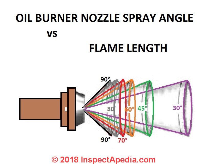
Oil Burner Electrode & Nozzle Guide Nozzle types, patterns, selection
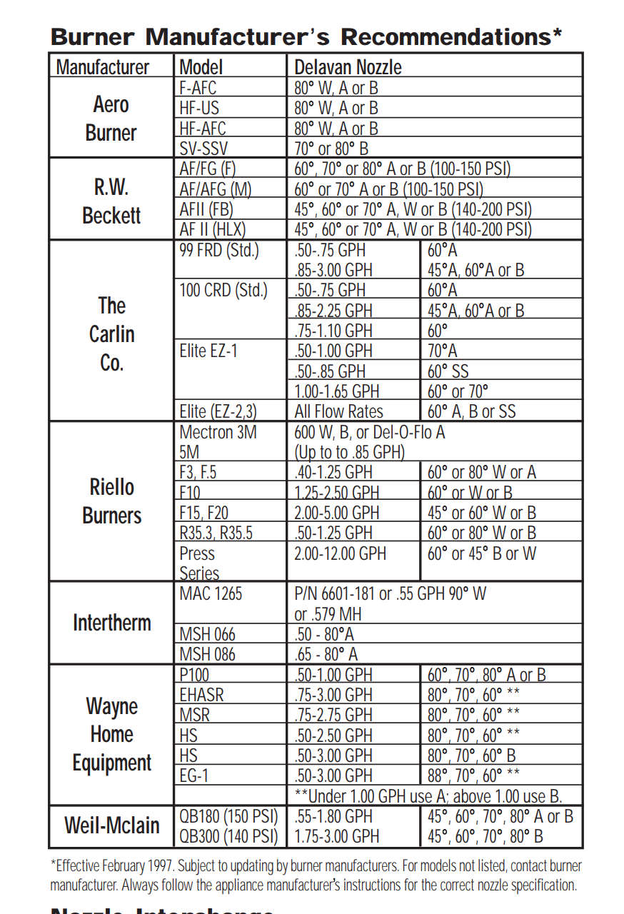
Oil Burning Temperature Chart A Visual Reference of Charts Chart Master

How to Adjust the Electrode (Points) Gap On Riello Oil Fired Burners

Oil Burner Electrode Adjustment Chart

Frost Fighter Heaters How to Set the Electrode Gaps (IDF Oil/Diesel

Prepare burner & site, Check/adjust "z" dimension "f" head Beckett
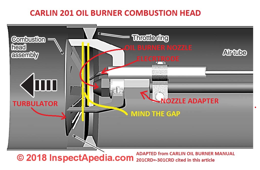
Oil Burner Electrode Assembly Inspection, Cleaning, Adjustment
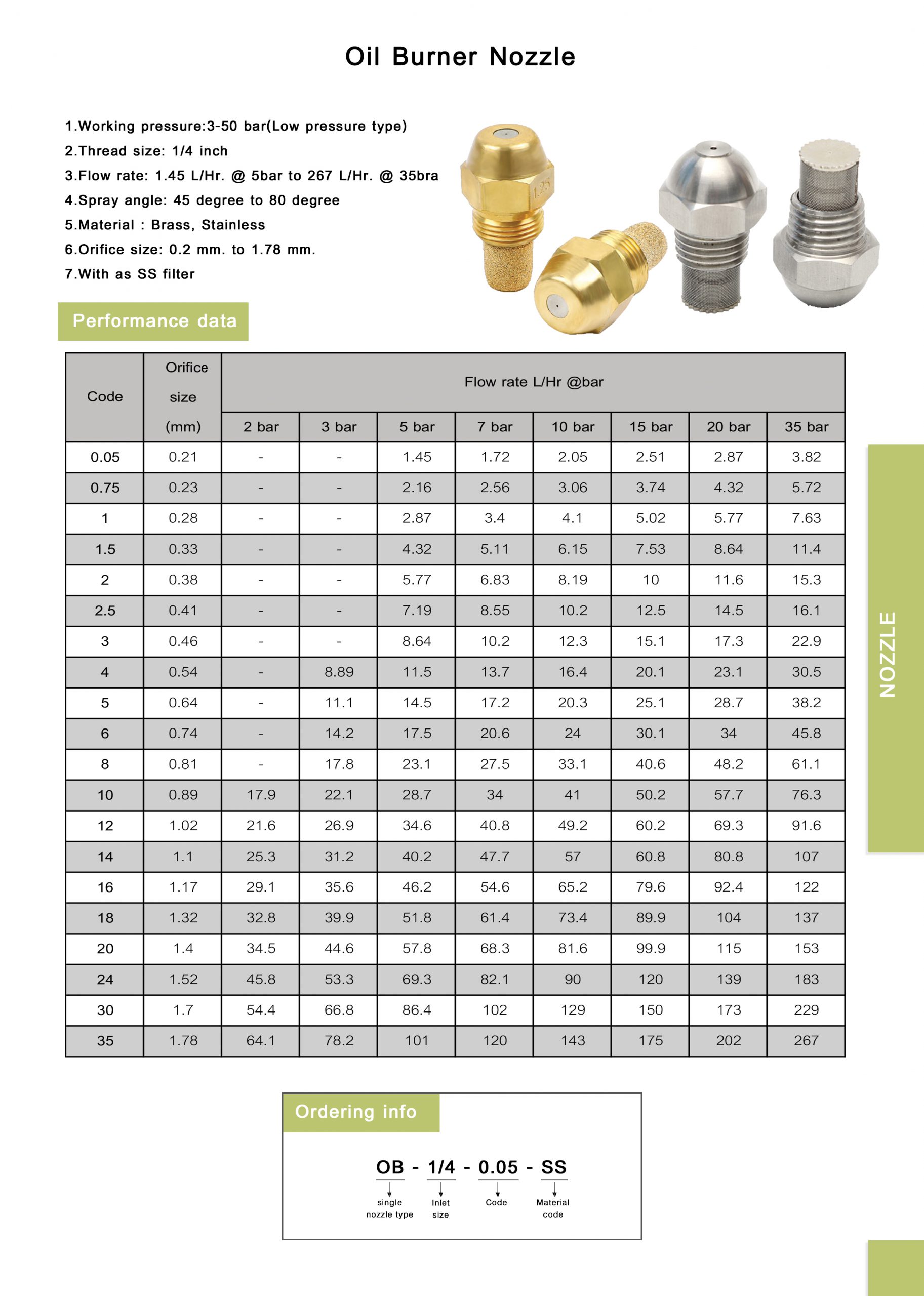
Oil Burner Electrode Adjustment Chart
Oil Burner Electrode Assembly Inspection, Cleaning, Adjustment
Web Critical That All Oil Fired Heating Equipment Be Installed Using Combustion Efficiency Test Equipment And The Burners Be Set To The Appliance Manufacturers Recommended Settings.
The “Z” Dimension Is Now Set.
For More Details, Refer To “ Connect Fuel Lines ” On Page 7.
Whether You Are Installing A New Burner, Solving A Problem, Or Conducting An Annual Service Call, You Eventually Get To The Point Where You Have To Adjust The Burner.
Related Post: