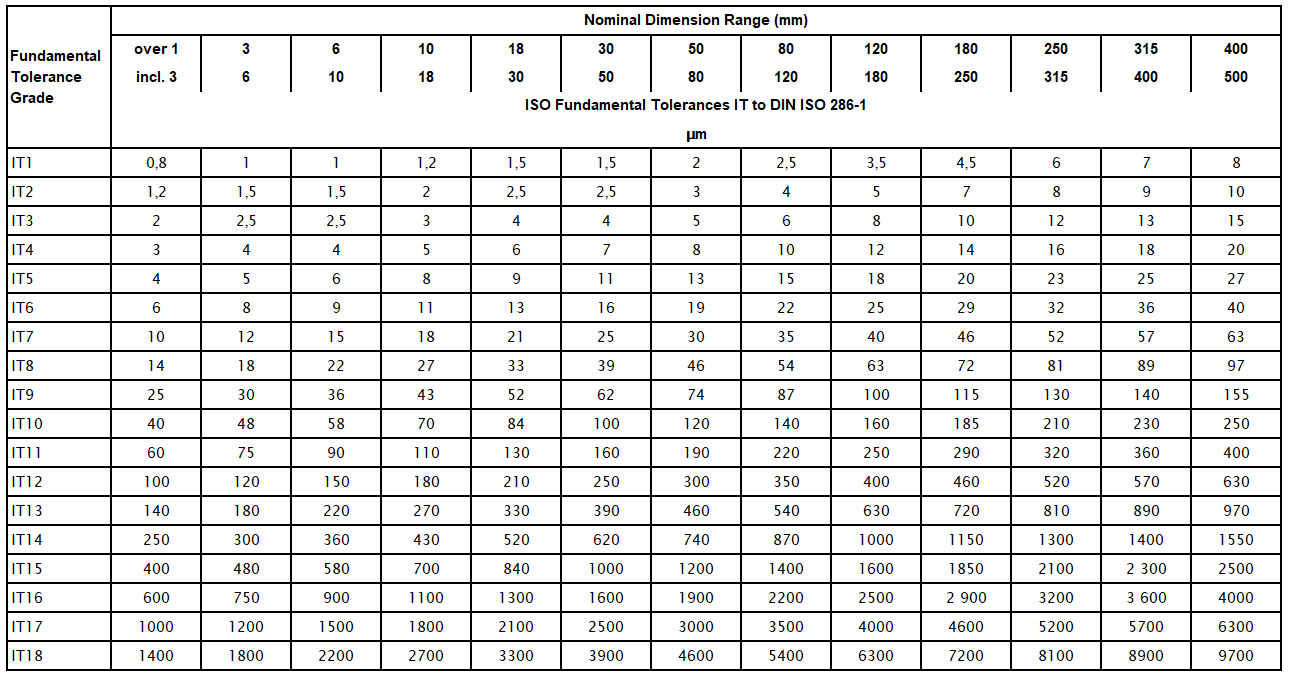
Iso 8015 Tolerance Chart
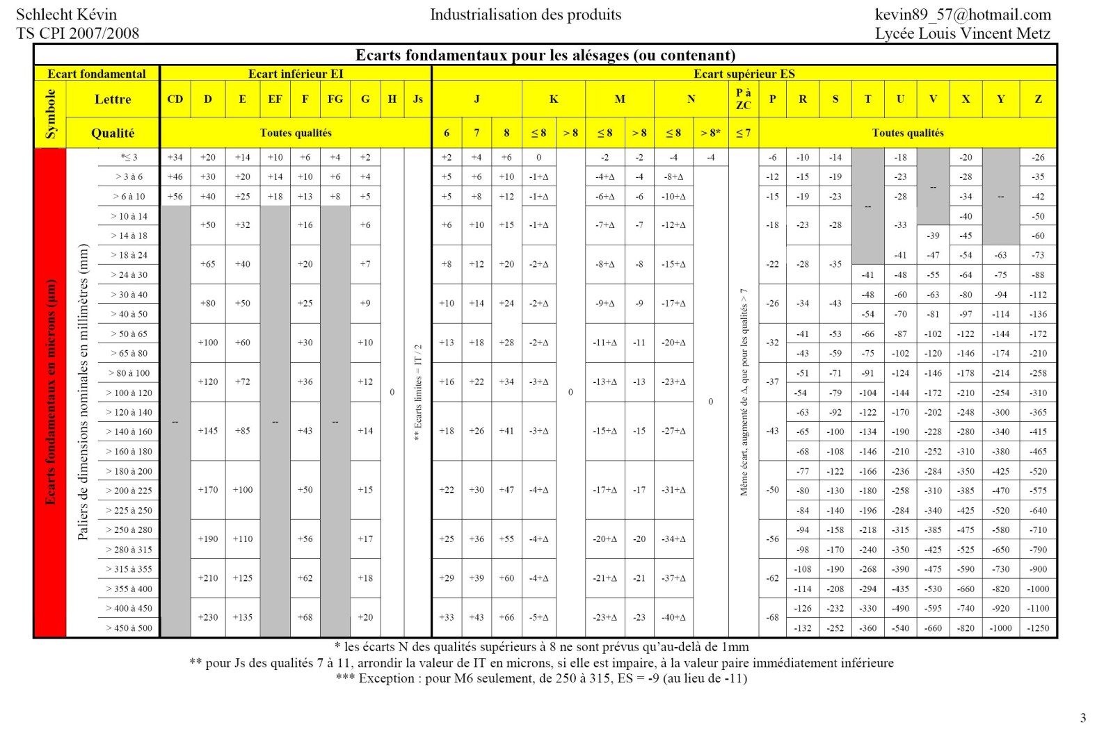
Iso 8015 Tolerance Chart - Web this is what our standard has to say about iso 8015: The default definition of size is. Specifies the principle of the relationship between dimensional tolerances and geometrical tolerances. Green = prefered tolerance classes per iso 286. This has been changed with this standard into the default rule: Where that is the case. British standard for metric limits and fits. L ≤ lmax, distance between two parallel tangential planes or the diameter of the minimum circumscribed cylinder. Datums and datum systems [7] iso 7200:2004, technical product documentation ? Swipe vertical scroll horizontal scroll page turn view mode. These dimensions are standardized limits for assemblies of mechanical component. Tolerances can be applied to holes and shafts as well as other shapes. Web 4.1 tolerancing principle as specified in iso 8015 general tolerances based on the tolerancing principle specified in iso 8015 are only to be applied when the drawing concerned contains the reference 'tolerancing to iso 8015'. Web. The tolerances of form and position) apply Data fields in title blocks and document. Web 4.1 tolerancing principle as specified in iso 8015 general tolerances based on the tolerancing principle specified in iso 8015 are only to be applied when the drawing concerned contains the reference 'tolerancing to iso 8015'. Find your data faster with our fits and tolerance calculator.. Web the first provides the charts for the fundamental deviations (g, j, etc.) and tolerance grades (7, 8, 9, etc.), out of which the limits of the tolerance classes (h7, g6, etc.) can be calculated. Tolerances can be applied to holes and shafts as well as other shapes. Tolerances for linear and angular dimensions without individual tolerance indications [6] iso. Datums and datum systems [7] iso 7200:2004, technical product documentation ? The tolerances of form and position) apply The schematic representation of the fit is also drawn by tolerance calculator. Web 4.1 tolerancing principle as specified in iso 8015 general tolerances based on the tolerancing principle specified in iso 8015 are only to be applied when the drawing concerned contains. Drawings, technical drawings, dimensional tolerances, angular tolerances, form tolerances, tolerances of position. Web january 1, 1985. These two standards outline the scope of tolerances. Web this is what our standard has to say about iso 8015: This standard has been revised by iso 8015:2011. Web the first provides the charts for the fundamental deviations (g, j, etc.) and tolerance grades (7, 8, 9, etc.), out of which the limits of the tolerance classes (h7, g6, etc.) can be calculated. The tolerances of form and position) apply The default definition of size is. Specifies the principle of the relationship between dimensional tolerances and geometrical tolerances.. This means that form was controled by indication of size. The default definition of size is. Web 4.1 tolerancing principle as specified in iso 8015 general tolerances based on the tolerancing principle specified in iso 8015 are only to be applied when the drawing concerned contains the reference 'tolerancing to iso 8015'. These two standards outline the scope of tolerances.. Web this is what our standard has to say about iso 8015: These dimensions are standardized limits for assemblies of mechanical component. Specifies the principle of the relationship between dimensional tolerances and geometrical tolerances. This has been changed with this standard into the default rule: Datums and datum systems [7] iso 7200:2004, technical product documentation ? The general geometrical tolerances (i.e. British standard for metric limits and fits. Find your data faster with our fits and tolerance calculator. Scribd is the world's largest social reading and publishing site. Iso 8015, ±tolerances and envelope requirement. Iso 8015, ±tolerances and envelope requirement. These two standards outline the scope of tolerances. The schematic representation of the fit is also drawn by tolerance calculator. This standard has been revised by iso 8015:2011. Drawings, technical drawings, dimensional tolerances, angular tolerances, form tolerances, tolerances of position. This means that form was controled by indication of size. Tolerances for linear and angular dimensions without individual tolerance indications [6] iso 5459:? This international standard specifies the principle of the relationship between dimensional (linear and angular) tolerances and geometrical tolerances. 3), geometrical product specifications (gps) ? Web the first provides the charts for the fundamental deviations (g, j, etc.) and tolerance grades (7, 8, 9, etc.), out of which the limits of the tolerance classes (h7, g6, etc.) can be calculated. Web the hole basis fits have four preferred hole tolerances (h11, h9, h8, and h7); British standard for metric limits and fits. Iso 8015, ±tolerances and envelope requirement. These dimensions are standardized limits for assemblies of mechanical component. Web 4.1 tolerancing principle as specified in iso 8015 general tolerances based on the tolerancing principle specified in iso 8015 are only to be applied when the drawing concerned contains the reference 'tolerancing to iso 8015'. The schematic representation of the fit is also drawn by tolerance calculator. Find your data faster with our fits and tolerance calculator. Web this is what our standard has to say about iso 8015: Swipe vertical scroll horizontal scroll page turn view mode. The tolerances of form and position) apply This has been changed with this standard into the default rule:
St Technica Tolerances Iso Tolerances vrogue.co

ISO 8015 Diameter Tolerance Chart

Din Iso 8015 Tolerance Chart Labb by AG
Din Iso 8015 Tolerance Chart Online Shopping

Table for Values of ISO Fundamental Tolerances Grades Engineersfield

Iso 8015 Tolerancing Chart Download

ISO Standard Tolerance Table

Iso 8015 gratuit tout

Din Iso 8015 Tolerance Chart Online Shopping

Iso Tolerance Chart A Visual Reference of Charts Chart Master
Tolerances Can Be Applied To Holes And Shafts As Well As Other Shapes.
These Two Standards Outline The Scope Of Tolerances.
Drawings, Technical Drawings, Dimensional Tolerances, Angular Tolerances, Form Tolerances, Tolerances Of Position.
Green = Prefered Tolerance Classes Per Iso 286.
Related Post: