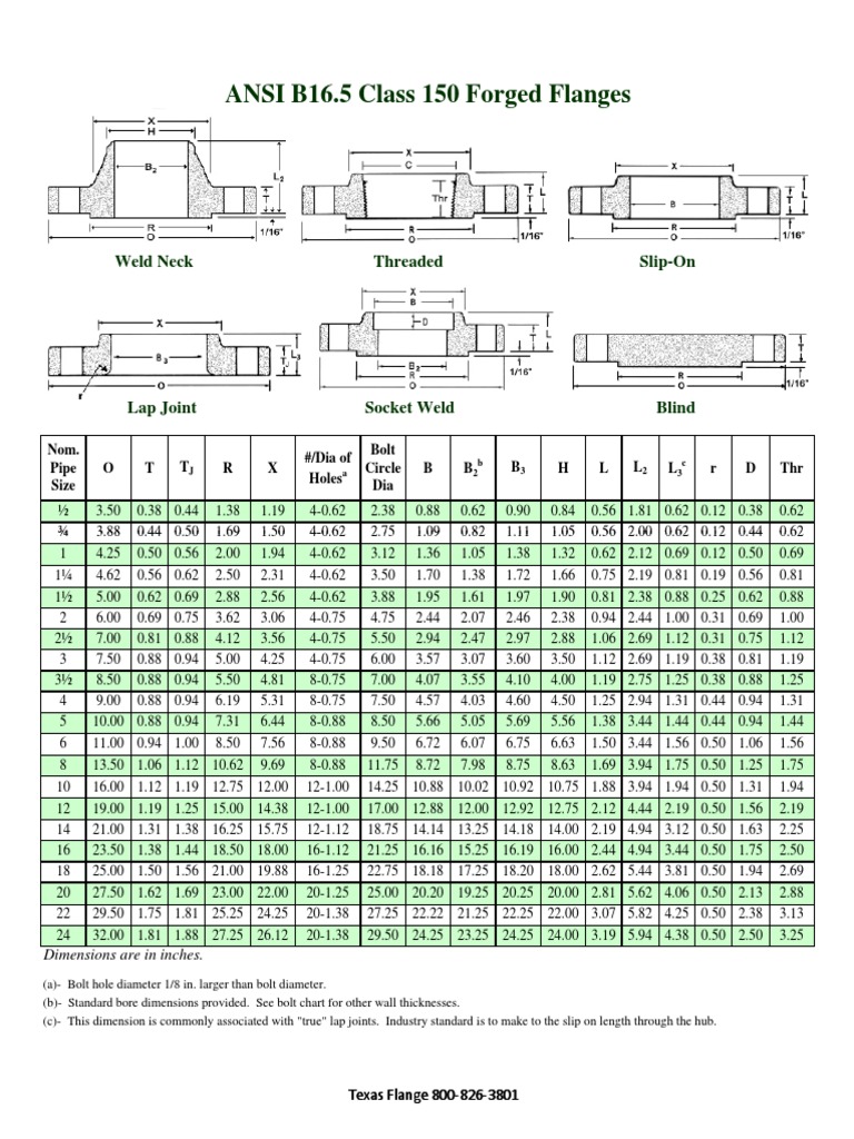
Flange Bolt Dimension Chart
Flange Bolt Dimension Chart - Web explore the comprehensive flange bolting chart at texas flange. D2 = diameter of raised face. The pn6 through pn64 pressure numbers are used to describe the pressure capacities of the ansi b16 5 flange as well. B = thickness of flange. Web dimensions are in inches unless otherwise indicated. Web pipe flange size & bolt chart. D2 = diameter of raised face. Web flange dimensions are covered in the following tables of asme b16.5 2020: Access essential information for secure and reliable connections in your piping projects. Web bolt specifications for standard ansi flanges cont. (1) this dimension is for the large end of the hub, which may be straight or tapered. D1 = diameter of bolt circle. B = thickness of flange. You will use a bolt and stud to connect flanges. 90 60 4 x 14. The length of the stud bolt does not include the height of the points. Dn = diameter nominal (size) a = flange. Ansi b16.47 series a class 150 flange pdf (for printing). 75 50 4 x 11. Flange dimensions are determined by the pipe size and the pressure class required for the application. Web instant flange bolt sizes and torque patterns: (2) when these flanges are required with flat face, the flat face may be either the full tf dimension thickness plus 0.06 in. D1 = diameter of bolt circle. Web bolt specifications for standard ansi flanges cont. 90 60 4 x 14. Or the tf dimension thickness. We measure our studs from end to end, which includes the chamfered points. Web the asme b16.5 flange can come in different pressure classes such as class 150 through class2500 and with different pressure numbers. Industry standard is to make to the slip on length through the hub. 90 60 4 x 14. Access essential information for secure and reliable connections in your piping projects. It was one of the first topics standardized by the iso committee as early as 1947 and is still used today. Or the tf dimension thickness. The diameter and length of the stud and bolt are covered in flange standard asme b16.5 & b16.47. Web flange dimensions are. Web flange dimensions are covered in the following tables of asme b16.5 2020: Web the following is chart data for ansi b16.5 flange dimensional data table for sizes 3 to 10 inches. Ansi b16.47 series a class 150 flange pdf (for printing). (2) length of point on studs and stud bolts shall be not less than one nor more than. The pn6 through pn64 pressure numbers are used to describe the pressure capacities of the ansi b16 5 flange as well. Or the tf dimension thickness. Larger sizes as well as intermediate sizes can be furnished. Ansi b16.47 series a class 150 flange pdf (for printing). Web the lengths of the machine bolts are measured from under the head to. D2 = diameter of raised face. D2 = diameter of raised face. Web the asme b16.5 flange can come in different pressure classes such as class 150 through class2500 and with different pressure numbers. Or the tf dimension thickness. Dn = diameter nominal (size) a = flange. D = diameter of bolt holes. Ansi b16.47 series a class 150 flange pdf (for printing). D2 = diameter of raised face. Web dimensions are in inches unless otherwise indicated. D1 = diameter of bolt circle. Ansi b16.47 series a class 150 flange pdf (for printing). 90 60 4 x 14. Dn = diameter nominal (size) a = flange. By nominal pipe size (nps) nps 0.5. Web bolt specifications for standard ansi flanges cont. It is the most commonly used worldwide thread system. Industry standard is to make to the slip on length through the hub. Flange dimensions are determined by the pipe size and the pressure class required for the application. Larger sizes as well as intermediate sizes can be furnished. Ansi b16.47 series a class 150 flange pdf (for printing). B = thickness of flange. By nominal pipe size (nps) nps 0.5. Nominal pipe size nps (inches) class 150. Or the tf dimension thickness. The length of the stud bolt does not include the height of the points. Access essential information for secure and reliable connections in your piping projects. N = number of bolts. Web the lengths of the machine bolts are measured from under the head to the top of the bolt. The length of the stud bolt does not include the height of the chamfers (points). You will use a bolt and stud to connect flanges. The pn6 through pn64 pressure numbers are used to describe the pressure capacities of the ansi b16 5 flange as well.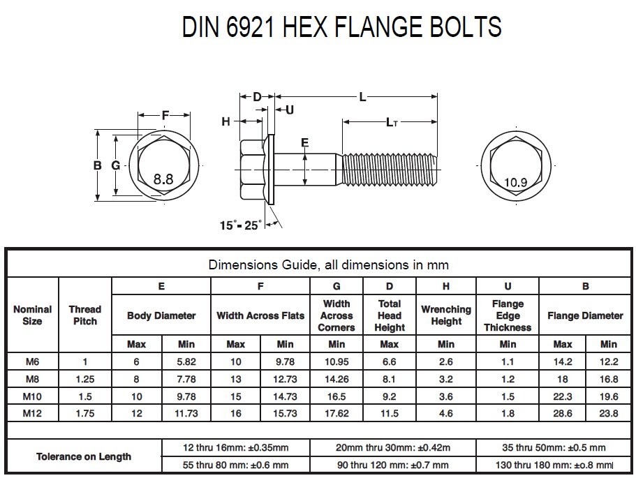
ANSI or DIN Standard Hex Flange Bolt (M6X16)

Flange Bolt Chart and Stud Size in mm

Technical Info Flange BoltUp Charts
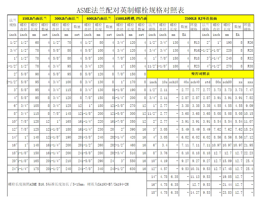
Bolt Dimension For ASME B16.5 flange
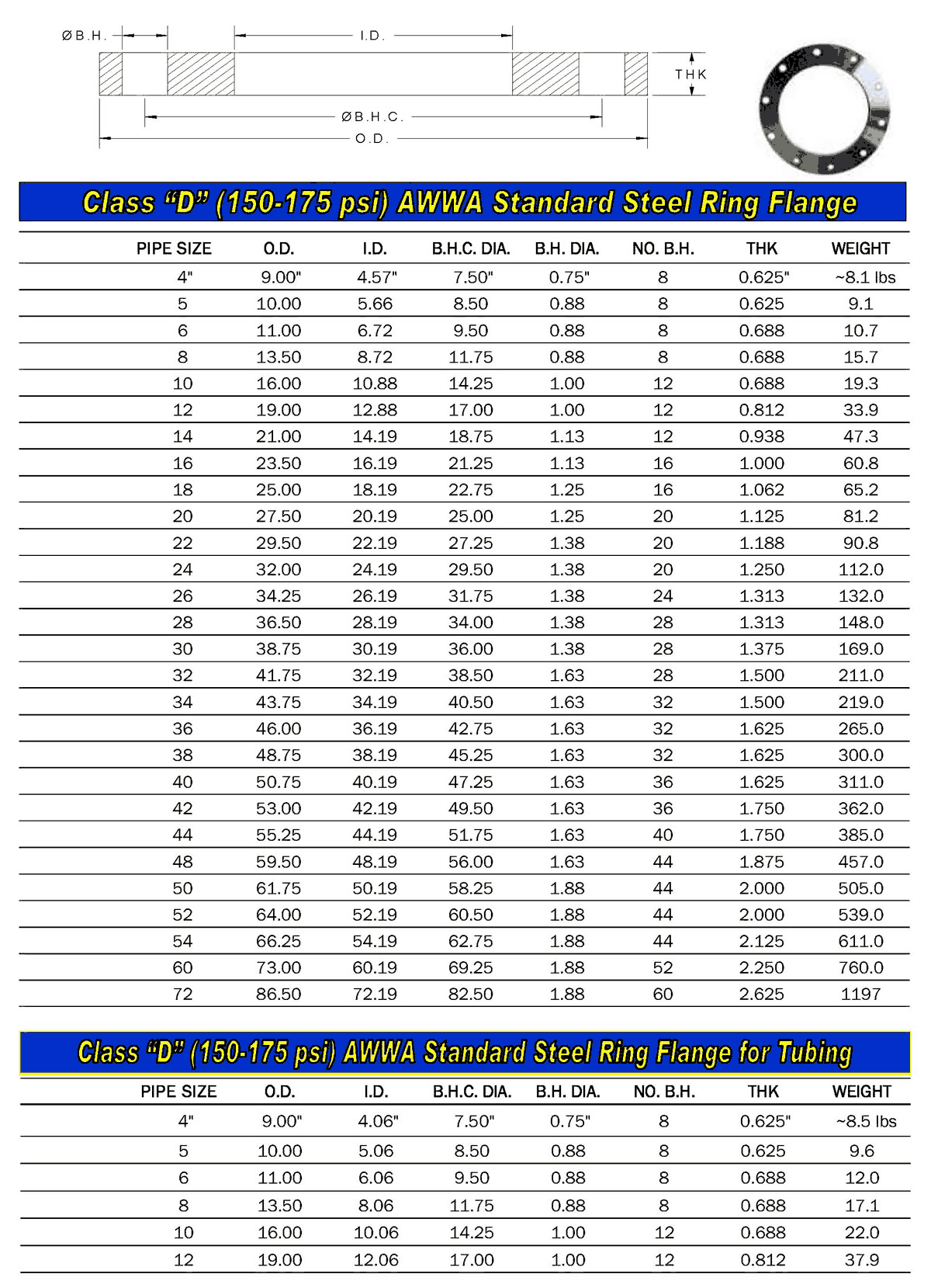
Standard Flange Sizes
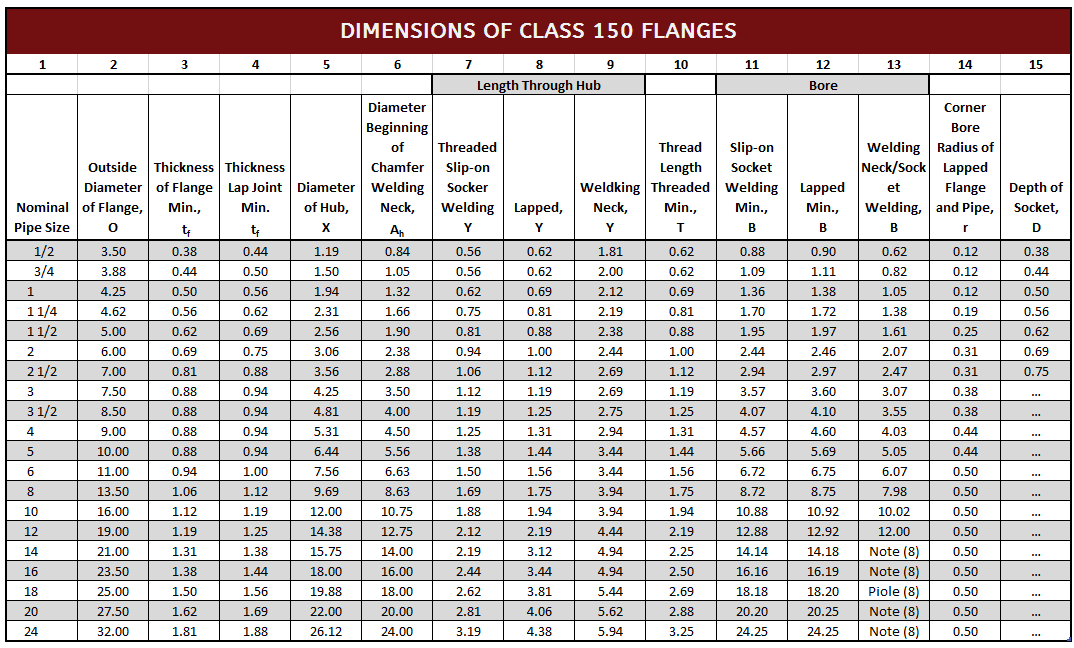
Flange Dimensions ANSI 150

Ansi B165 Flange Dimensions Charts And Tables Images and Photos finder

flange OD PCD hole dia PDF Free download/pipe flange dimension chart
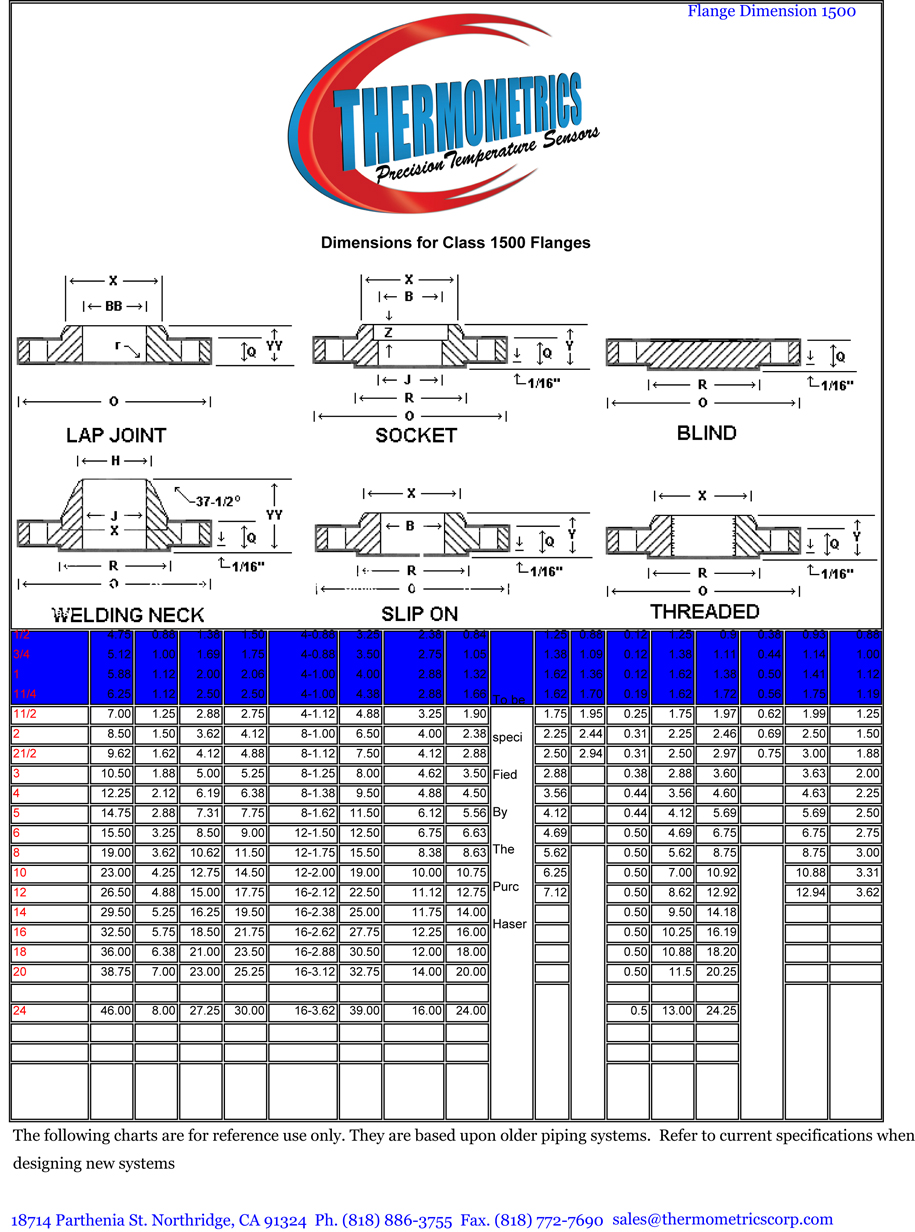
Thermometrics Corporation Flanges
Printable Flange Size Chart Printable Word Searches
Web Explore The Comprehensive Flange Bolting Chart At Texas Flange.
Web The Following Is Chart Data For Ansi B16.5 Flange Dimensional Data Table For Sizes 3 To 10 Inches.
Web Dimensions Are In Inches Unless Otherwise Indicated.
Links To The Flange Dimensions Charts Maintained By Flange Bolt Chart.
Related Post:
