Engineering Symbols For Drawings
Engineering Symbols For Drawings - Note the comparison with the iso standards. These are a set of symbols that describe the weld, the weld leg size, as well as giving processing and finishing information. Web engineering drawing notes and legends. Used in bill of materials and in component. In this guide you’ll learn: The first tool in your engineering drawing toolbox is the drawing view. This list includes abbreviations common to the vocabulary of people who work with engineering drawings in the manufacture and inspection of parts and assemblies. Arcs are also dimensioned on drawing with a radius. Web gd&t flatness is a common symbol that references how flat a surface is regardless of any other datum’s or features. After selecting many elements at once, all drawing annotations will move together. Iso 1101 g&t sumbols and definitions. (kbr), an engineering company, announced on monday that it has bagged a contract from oci global or oci to design and deploy its proprietary operator training simulator for. For example, engineering symbols are used in technical drawings to convey the specific geometry and other details about pieces of equipment or components. Web familiar with. A dimension listed on an engineering drawing is known as the _______ _______. A generic engineering drawing can be divided into the following five major areas or parts. For example, r6 means the circle has a radius of 6mm. The notes and legends section of a. Used in bill of materials and in component. Make a the lowest point of the drawing. The included collection of predesigned mechanical drafting symbols, machining drawing symbols, and machinist symbols helps in drawing mechanical diagrams and schematics, mechanical drafting symbols chart or mechanical drawing quickly, easily, and effectively. The mechanical engineering branch, mechanical systems division, has been delegated Web how to read an engineering drawing symbol. Web the. These are a set of symbols that describe the weld, the weld leg size, as well as giving processing and finishing information. Unlike a model, engineering drawings offer more specific detail and requirements, such as: The following tables show how to construct the symbols. As an integral part of cad/cam technology, cnc design is used to develop and produce. Common. To limit errors caused by personal interpretation, engineering drawings and diagrams are. Web engineering drawing notes and legends. For example, engineering symbols are used in technical drawings to convey the specific geometry and other details about pieces of equipment or components. Often models are used in conjunction with engineering drawings to show a good visual representation. Learners examine the drawing. Web how to read an engineering drawing symbol. Web the table shows dimensioning symbols found on engineering and mechanical drawings. The notes and legends section of a. Circular runout is most often specified on an engineering drawing where the referenced rotates relative to the specified datum feature. This is a complete guide to the types of holes found in machining. The flatness tolerance references two parallel planes (parallel to the surface. Iso 1101 g&t sumbols and definitions. As an integral part of cad/cam technology, cnc design is used to develop and produce. Learn the ins and outs of engineering drawing standards, such as iso and ansi, which govern the symbols, abbreviations, and notations used in. Note the comparison with the. This list includes abbreviations common to the vocabulary of people who work with engineering drawings in the manufacture and inspection of parts and assemblies. The mechanical engineering branch, mechanical systems division, has been delegated These symbols provide an information about gears, springs, bearings, etc. The flatness tolerance references two parallel planes (parallel to the surface. It comes in useful if. After selecting many elements at once, all drawing annotations will move together. Circular runout is most often specified on an engineering drawing where the referenced rotates relative to the specified datum feature. Web engineering drawing abbreviations and symbols are used to communicate and detail the characteristics of an engineering drawing. How each type of hole is used in engineering. The. A generic engineering drawing can be divided into the following five major areas or parts. Iso 1101 g&t sumbols and definitions. Web this is a massive article with well over 4000 words, over 50 subheadings, and symbol drawings. Web a good design drawing can indicate all the details needed to produce a mechanical cnc milling part in an easy way.. Circular runout is most often specified on an engineering drawing where the referenced rotates relative to the specified datum feature. A radius dimension is preceded by an `r´. In the quiz that completes the activity, they associate these symbols with machining applications. The different types of holes used in machining. Web how to read an engineering drawing symbol. Any needed height h 2 h h 2 h 60° 2 h identification letter datum feature symbol datum target symbol target point and. This list includes abbreviations common to the vocabulary of people who work with engineering drawings in the manufacture and inspection of parts and assemblies. Web gd&t flatness is a common symbol that references how flat a surface is regardless of any other datum’s or features. Learners examine the drawing symbols used for counterbore, countersink, spotface, radius, diameter, and depth. Arcs are also dimensioned on drawing with a radius. Most symbols have been in y14.5 since at least 1994. Web there are literally hundreds of engineering drawing symbols and they’re used in a variety of ways. A generic engineering drawing can be divided into the following five major areas or parts. The included collection of predesigned mechanical drafting symbols, machining drawing symbols, and machinist symbols helps in drawing mechanical diagrams and schematics, mechanical drafting symbols chart or mechanical drawing quickly, easily, and effectively. (kbr), an engineering company, announced on monday that it has bagged a contract from oci global or oci to design and deploy its proprietary operator training simulator for. Iso 1101 g&t sumbols and definitions.
Standard Engineering Drawing Symbols

Mechanical Drawing Symbols Electrical Symbols, Electrical Diagram

Mechanical Engineering Drawing Symbols Pdf Free Download at

How To Read Architectural Drawings Symbols The Architect

Engineering Drawing Symbols And Their Meanings Pdf at PaintingValley

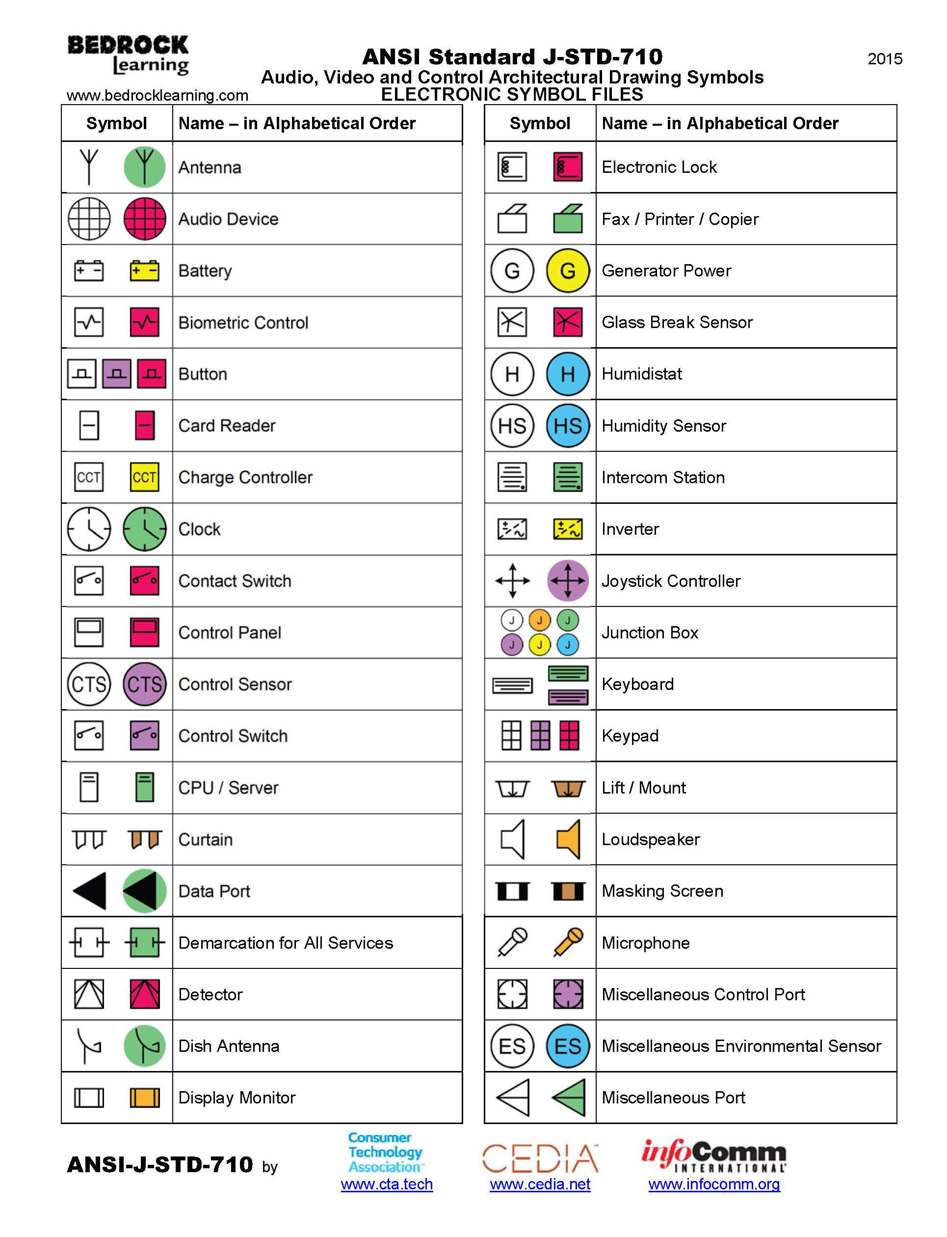
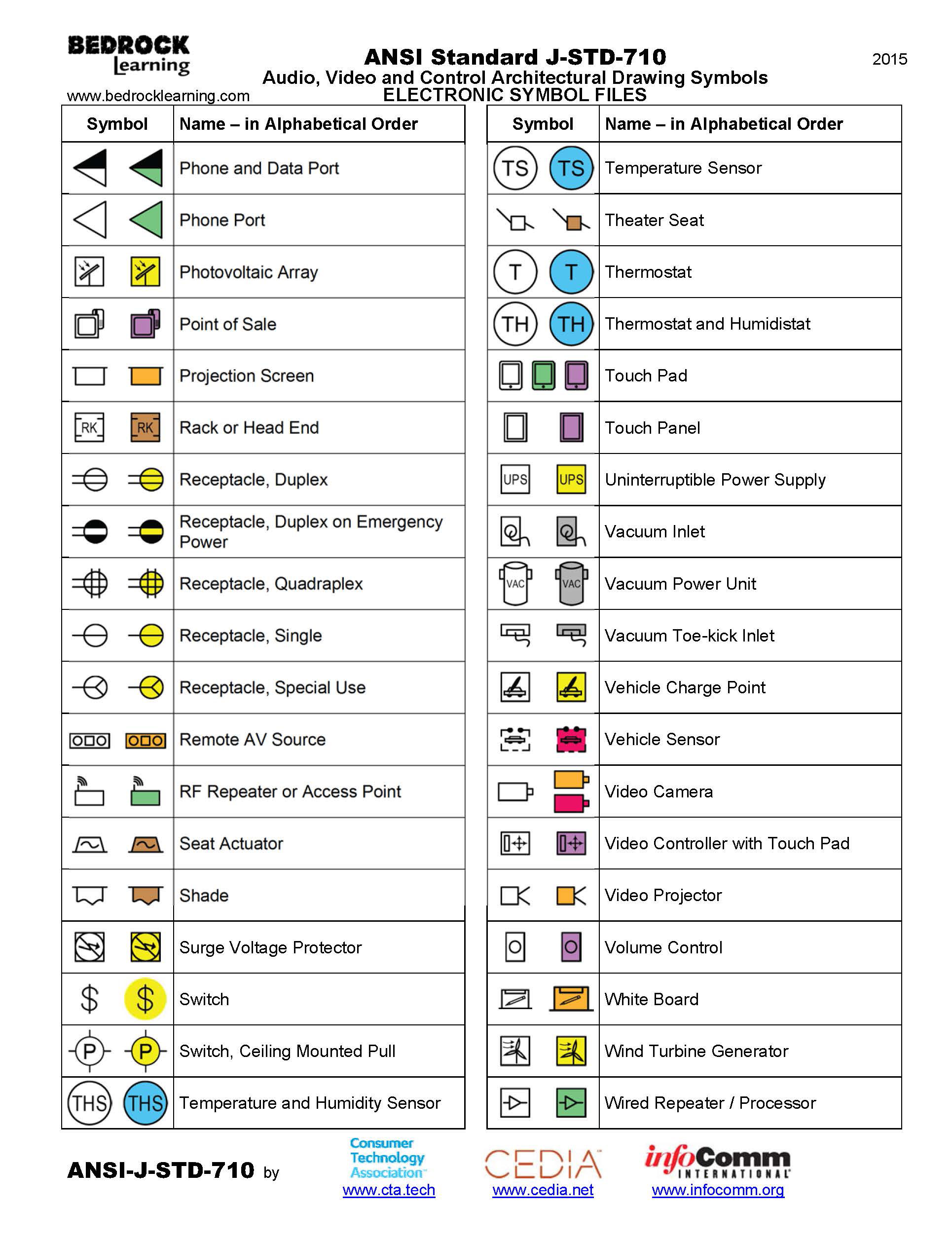
ANSI Standard JSTD710 Architectural Drawing Symbols Bedrock Learning

Civil Engineering Drawing Symbols And Their Meanings at PaintingValley

Engineering Drawing Symbols And Their Meanings Pdf at PaintingValley

Mechanical Engineering Drawing Symbols Pdf Free Download at

ANSI Standard JSTD710 Architectural Drawing Symbols Bedrock Learning
Note The Comparison With The Iso Standards.
In This Guide You’ll Learn:
Web The Table Shows Dimensioning Symbols Found On Engineering And Mechanical Drawings.
A Dimension Listed On An Engineering Drawing Is Known As The _______ _______.
Related Post: