Engineering Drawing Details
Engineering Drawing Details - One can pack a great deal of information into an isometric drawing. Do not dimension the drawing. Web engineering drawing is a specialized form of communication that uses a strict set of symbols, standards, and perspectives to depict mechanical, electrical, or structural designs. Web engineering drawing is the practice of applying precise measurements and guidelines to depict the structure, dimensions, and other technical details of an object or system. If you find any mistakes, missing information or have a question, contact: Web unlike a 3d model, an engineering drawing offers a lot more specific information and requirements, including: Creating drawings using the cad software is a straightforward process; The mechanical engineering branch, mechanical systems division, has been delegated Because there is no large space on a drawing to contain all the text to illustrate the image, abbreviations, and symbols are often used in engineering drawings to communicate the characteristics of the product to be. Usually prepared by the design team or contractors, these drawings emphasize the authentic construction details for final project acceptance and archival. They are a good visual representation of the desired item,. Web any engineering drawing should show everything: If you find any mistakes, missing information or have a question, contact: Web engineering drawing is a specialized form of communication that uses a strict set of symbols, standards, and perspectives to depict mechanical, electrical, or structural designs. These meticulously crafted blueprints hold. The mechanical engineering branch, mechanical systems division, has been delegated It is used in ships for navigation. Usually prepared by the design team or contractors, these drawings emphasize the authentic construction details for final project acceptance and archival. These drawings are essentially the blueprints or plans for manufacturing a wide array of products and structures. Web the gsfc engineering drawing. A good rule to remember is that the person drafting or creating the drawing is the link between the inventor / designer and the manufacturer. It acts as a visual language that communicates the intricate details of engineering concepts to various professionals involved in design, manufacturing, construction, and. Tdot cadd support 1200 james k. These drawings are essentially the blueprints. Therefore, any surface that is not in line with the three major axis needs its own projection plane to show the features correctly. The title block appears either at the top or bottom of an engineering drawing. All the information on the drawing should be clear and precises and nothing should be left for interpretation. But as we are using. Web engineering drawing abbreviations and symbols are used to communicate and detail the characteristics of an engineering drawing. Web the gsfc engineering drawing standards manual is the official source for the requirements and interpretations to be used in the development and presentation of engineering drawings and related documentation for the gsfc. They are a good visual representation of the desired. These drawings are essentially the blueprints or plans for manufacturing a wide array of products and structures. Web 3 precision tools. This makes understanding the drawings simple with little to no personal. It is used in ships for navigation. Web any engineering drawing should show everything: Read this first to find out crucial information about the drawing, including: Web unlike a 3d model, an engineering drawing offers a lot more specific information and requirements, including: They are introduced to standard paper. Usually prepared by the design team or contractors, these drawings emphasize the authentic construction details for final project acceptance and archival. Technical standards exist to. The mechanical engineering branch, mechanical systems division, has been delegated Any engineering drawing should show everything: Web although engineers created the engineering drawings in the past by hand, today, they are primarily done in cad software like autodesk fusion 360. [4] the name and contact information for the company producing or distributing the part. This list includes abbreviations common to. One can pack a great deal of information into an isometric drawing. Engineering drawing is a critical part of almost all engineering projects. Web engineering drawing basics explained. Web archived standard drawings. Web the gsfc engineering drawing standards manual is the official source for the requirements and interpretations to be used in the development and presentation of engineering drawings and. A dimension listed on an engineering drawing is known as the _______ _______. 14 february 2000 for use by the department of defense (dod). Therefore, any surface that is not in line with the three major axis needs its own projection plane to show the features correctly. If you find any mistakes, missing information or have a question, contact: Web. A complete understanding of the object should be possible from the drawing. Web engineering drawings serve as the backbone of various industries, providing a visual representation of designs, dimensions, and specifications. Web and this is my friend, how you create a section view on the engineering drawing. Web engineering drawing basics explained. 3d models are good to have and are usually (especially nowadays) used in conjunction with drawings. These drawings are essentially the blueprints or plans for manufacturing a wide array of products and structures. An engineering drawing is a subcategory of technical drawings. We can find that engineering drawing serves many critical applications: Web engineering working drawings basics page 8 of 22 parallel to the object surface. If the isometric drawing can show all details and all dimensions on one drawing, it is ideal. A dimension listed on an engineering drawing is known as the _______ _______. Web a good design drawing can indicate all the details needed to produce a mechanical cnc milling part in an easy way. Usually prepared by the design team or contractors, these drawings emphasize the authentic construction details for final project acceptance and archival. The purpose is to convey all the information necessary for manufacturing a product or a part. One can pack a great deal of information into an isometric drawing. Civil engineering drawings are the bedrock of any construction project, acting as the visual roadmap that guides engineers, architects, and construction teams toward successful project completion.
Lecture Notes Engineering Drawing Part 5

how to read civil engineering drawings Engineering Feed

How to prepare a technical drawing for CNC machining 3D Hubs
Engineering Drawing Views & Basics Explained Fractory
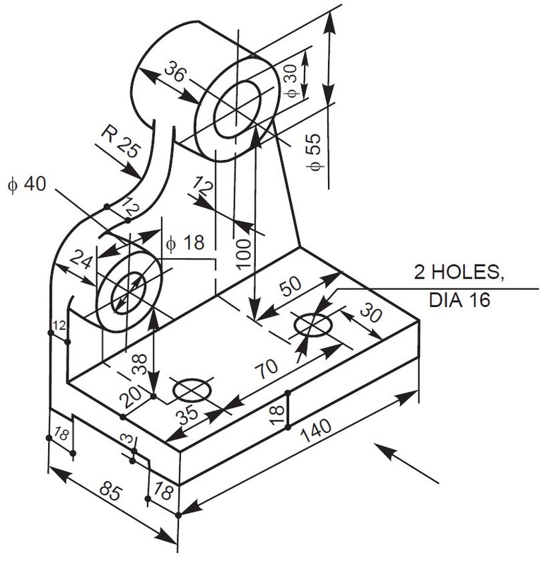
Engineering Drawing at GetDrawings Free download
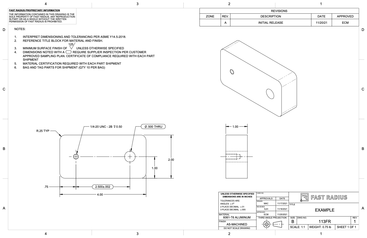
What to Include in Your Engineering Drawing Fast Radius
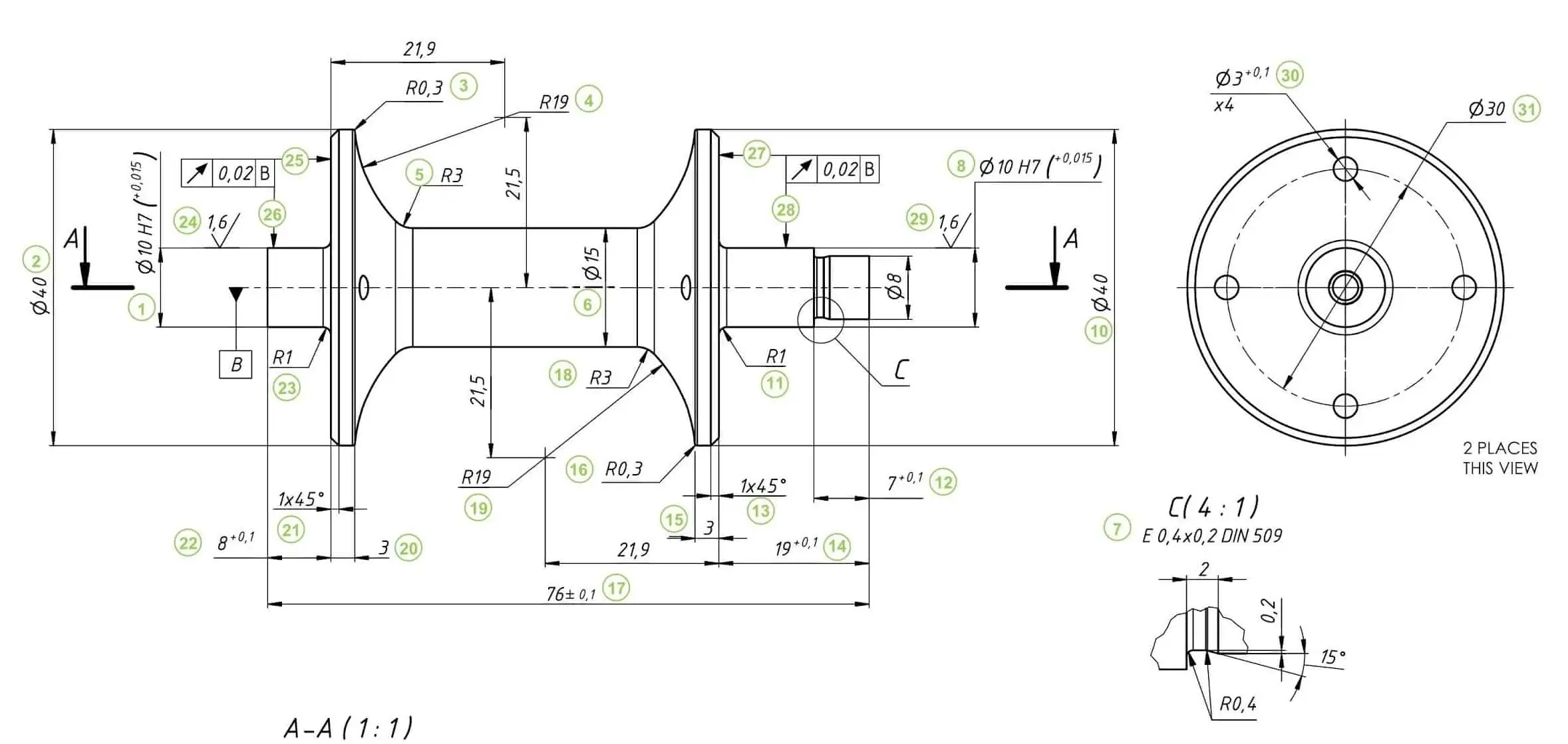
How To Prepare A Perfect Technical Drawing Xometry Europe

Mechanical Engineering Drawing and Design, Everything You Need To Know

2D Technical Drawings CNC Machining Service
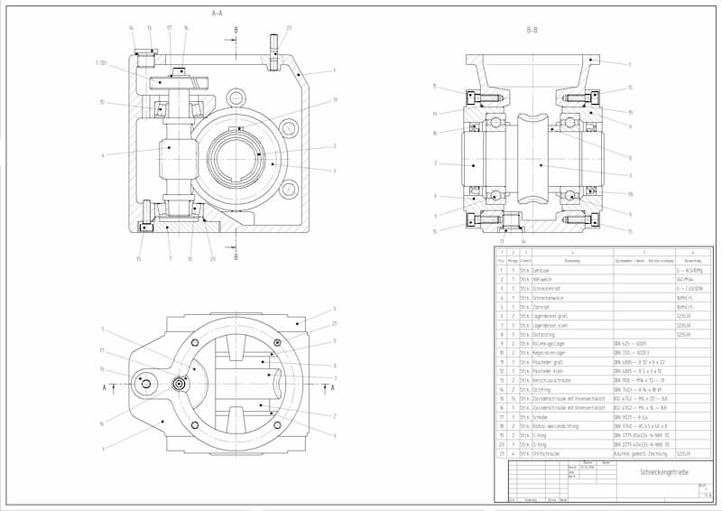
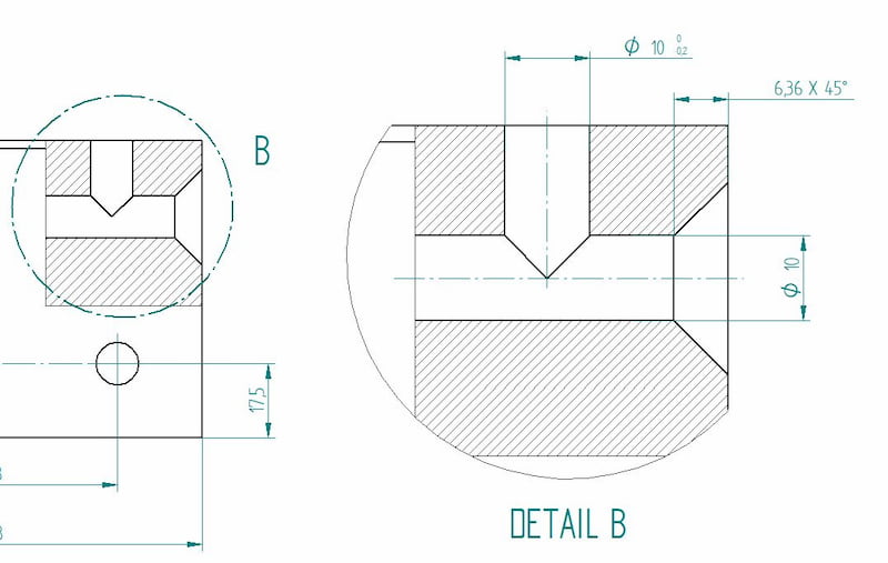
Engineering Drawing Views & Basics Explained Fractory
Web Although Engineers Created The Engineering Drawings In The Past By Hand, Today, They Are Primarily Done In Cad Software Like Autodesk Fusion 360.
However, If The Object In Figure 2 Had A Hole On The Back.
Web Students Are Introduced To Detail Drawings And The Importance Of Clearly Documenting And Communicating Their Designs.
All The Information On The Drawing Should Be Clear And Precises And Nothing Should Be Left For Interpretation.
Related Post: