Electronics Drawings
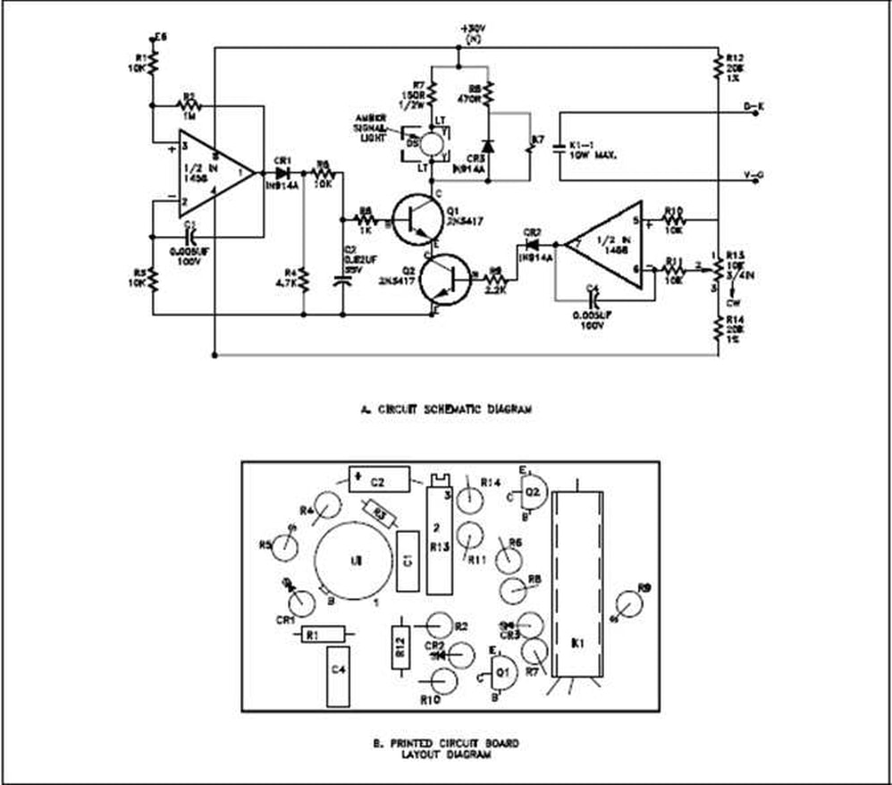
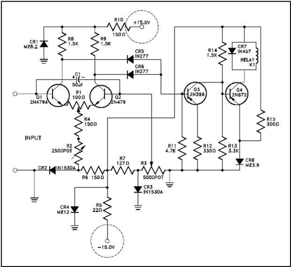
Electronics Drawings - This makes the whole project easier to document and maintain, and also makes communication easier between the hw designer (s) and the sw designer (s) in case they are different people. Electrical symbols and electronic circuit symbols are used for drawing schematic diagram. Block diagrams provide a means of representing any type of electronic circuit or system in a simple graphic. Shown in figure 4 is the schematic for a circuit and the same circuit drawn in pictorial or layout format for comparison. When three or more lines touch each other or cross each other and a node is placed at the intersection, this represents the lines or wires. Lines connect fuses, switches, capacitors, inductors, and more. Design circuits online in your browser or using the desktop application. Master the analysis and design of electronic systems with circuitlab's free, interactive, online electronics textbook. With symbols ranging from amplifiers to vacuum tubes, as well as the ability to build custom symbols, you are able to design nearly any circuit. As the name implies, block diagrams represent any part. Browse circuits made by other users of circuit diagram. Electrical symbols and electronic circuit symbols are used for drawing schematic diagram. Web electrical symbols & electronic symbols. Then we'll talk about how those symbols are connected on schematics to create a model of a circuit. Lines connect fuses, switches, capacitors, inductors, and more. Then we'll talk about how those symbols are connected on schematics to create a model of a circuit. Web electrical symbols & electronic symbols. This tutorial should turn you into a fully literate schematic reader! This comprehensive guide will delve into the different types of electrical and electronics engineering drawings, exploring their distinct features, applications, and significance in. There are. Circuit diagrams or schematic diagrams show electrical connections of wires or conductors by using a node as shown in the image below. Shown in figure 4 is the schematic for a circuit and the same circuit drawn in pictorial or layout format for comparison. Welcome to digikey's free online schematic and diagramming tool. Open source eda / electronics cad software. Browse circuits made by other users of circuit diagram. There are some standard symbols to represent the components in a circuits. We'll go over all of the fundamental schematic symbols: Circuit diagram is a free application for making electronic circuit diagrams and exporting them as images. It is available for free download. In electrical and electronics engineering, we use different types of drawings or diagrams to represent a certain electrical system or circuit.these electrical circuits are represented by lines to represent wires and symbols or icons to represent electrical and electronic. Lines connect fuses, switches, capacitors, inductors, and more. With symbols ranging from amplifiers to vacuum tubes, as well as the ability. When three or more lines touch each other or cross each other and a node is placed at the intersection, this represents the lines or wires. Use schematic capture, create pcb designs and view. Web kicad's 3d viewer allows easy inspection of your pcb to check mechanical fit and to preview your finished product. Web electronics drafting is a crucial. Block diagrams provide a means of representing any type of electronic circuit or system in a simple graphic. A node is simply a filled circle or dot. When three or more lines touch each other or cross each other and a node is placed at the intersection, this represents the lines or wires. Web create electronic circuit diagrams online in. They depict every component in a circuit, the component’s technical information (such as its ratings), and how each component is wired into the circuit. Use schematic symbols to layout the components of your circuit and make electrical connections. This tutorial should turn you into a fully literate schematic reader! Use schematic capture, create pcb designs and view. The process of. This article gives some of the frequently used symbols for drawing the circuits. Graphical symbols not only identify a components position but the type of electrical element too. Web it supports circuit drawing, layout developing and circuit simulation. In electrical and electronics engineering, we use different types of drawings or diagrams to represent a certain electrical system or circuit.these electrical. Use schematic capture, create pcb designs and view. Block diagrams are the simplest type of drawing. This tutorial should turn you into a fully literate schematic reader! Electrical symbols or electronic circuits are virtually represented by circuit diagrams. Graphical symbols not only identify a components position but the type of electrical element too. Graphical symbols not only identify a components position but the type of electrical element too. An electrical drawing is a type of technical drawing that shows information about power, lighting, and communication for an engineering or architectural project. Circuit diagrams or schematic diagrams show electrical connections of wires or conductors by using a node as shown in the image below. Block diagrams are the simplest type of drawing. This makes the whole project easier to document and maintain, and also makes communication easier between the hw designer (s) and the sw designer (s) in case they are different people. With symbols ranging from amplifiers to vacuum tubes, as well as the ability to build custom symbols, you are able to design nearly any circuit. Use the same signal names in the schematic as in the source code of your firmware. Open an wiring diagram or circuit drawing template—not just a blank screen. Electrical symbols and electronic circuit symbols are used for drawing schematic diagram. Browse circuits made by other users of circuit diagram. Shown in figure 4 is the schematic for a circuit and the same circuit drawn in pictorial or layout format for comparison. Reading electrical diagrams is one of the most important skills for anyone in a troubleshooting. They depict every component in a circuit, the component’s technical information (such as its ratings), and how each component is wired into the circuit. Web kicad's 3d viewer allows easy inspection of your pcb to check mechanical fit and to preview your finished product. Web circuit diagram connections. Circuit diagram is a free application for making electronic circuit diagrams and exporting them as images.
what is electrical electronic drawing Wiring Diagram and Schematics

Electronic Schematics Symbols And Meanings

what is electrical electronic drawing Wiring Diagram and Schematics

A illustration of pencil drawing of electronic gadget Stock fotó

Introduction to Basic Electronics, Electronic Components and Projects

Electronics and Engineering. Printed Drawings of Electrical Circuits

Electronics components set drawings Royalty Free Vector

Electronics by Reza Razazzadeh Sick drawings, Industrial design

A Set of Hand Drawn Doodles of Electronic Gadget. Stock Vector

Hand Drawn Green Pen Electronic Gadgets Set. Sketches of Computer
The Process Of Electronics Drafting Requires A High Level Of Technical Skill And Knowledge, As Well As A Thorough Understanding Of The Principles Of Electronics And.
Web Upload And Share Your Circuit Designs.
There Are Some Standard Symbols To Represent The Components In A Circuits.
This Comprehensive Guide Will Delve Into The Different Types Of Electrical And Electronics Engineering Drawings, Exploring Their Distinct Features, Applications, And Significance In.
Related Post: