Bend Radius Chart For Sheet Metal
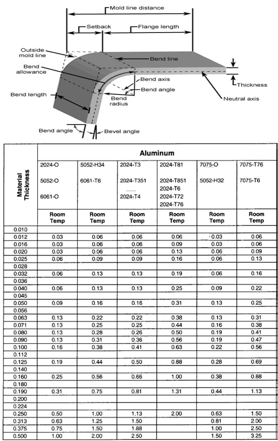
Bend Radius Chart For Sheet Metal - Web we recommend a minimum bend radius of 1t for all sheet metal parts. For starters, the material thickness in any sheet metal part should be consistent. 1 time the thickness of the sheet. Web there is a minimum bending radius that should always be maintained in sheet metal design practices, and this minimum br is displayed as a multiple of the specific raw. Use the minimum bend dimension values in the charts below for your minimum closeness of cutout to a bend. Input material thickness and and inner radius to get the k factor, y factor, neutral layer. Web the bending force table below helps you identify the minimum flange length b (mm) and inside radii ir (mm) according to material thickness t (mm). 1.5 times the thickness of the sheet. Web you can derive the bend allowance (ba) by using the k , bend radius (r), bend angle (a) and material thickness using the formula below. Web the actual calculations should be based on the pressure and bending die of your own sheet metal processing facility. 1.5 times the thickness of the sheet. Web other sheet metal design considerations. Web bend allowance is dependent on the inside formed radius. Web the bend radius refers to the minimum radius a sheet metal can be bent without causing damage or distortion. They all start out as a. We go beyond the general rules of sheet metal. Web the bend radius refers to the minimum radius a sheet metal can be bent without causing damage or distortion. Web sheet metal bend radius is an essential factor to consider during metal forming processes like air bending or metal bending with a press brake. 1 common bend radius design mistakes.. Web a sheet metal bend radius chart is a valuable tool that provides engineers and fabricators with essential information. Web you can derive the bend allowance (ba) by using the k , bend radius (r), bend angle (a) and material thickness using the formula below. Web other sheet metal design considerations. The inside radius for mild steel is. Web we. Radius is the minimum producible inside radius for this material and not the recommended inside radius that you see on the bend allowance chart. They all start out as a. Web a sheet metal bend radius chart is a valuable tool that provides engineers and fabricators with essential information. Web the bending force table below helps you identify the minimum. 1.5 times the thickness of the sheet. Web the actual calculations should be based on the pressure and bending die of your own sheet metal processing facility. The lower v die opening determines the inside radius (i.r.) of a formed part. You can also see the die. It typically lists various materials and their corresponding. Web therefore, the structural design of bent parts should avoid overly small bending corner radii. Web a sheet metal bend radius chart is a valuable tool that provides engineers and fabricators with essential information. 2.0.1 unable to unfold part, sheet metal bend. 1.5 times the thickness of the sheet. Web the tables below show bend radii and minimum bend sizes. Web other sheet metal design considerations. Bending is a process whereby a force is applied to sheet metal which causes it to bend at an angle and form the desired shape. Web the tables below show bend radii and minimum bend sizes for materials and tooling combinations stocked by protocase. Web ba = [ (0.017453 × inside radius) + (0.0078. We go beyond the general rules of sheet metal. Web the bending force table below helps you identify the minimum flange length b (mm) and inside radii ir (mm) according to material thickness t (mm). You can also see the die. That said, some caveats exist. Aluminum sheet metal size table chart. Web you can derive the bend allowance (ba) by using the k , bend radius (r), bend angle (a) and material thickness using the formula below. 1.5 times the thickness of the sheet. We go beyond the general rules of sheet metal. The inside radius for mild steel is. The length of the neutral axis is calculated as a bend. Web the bend radii listed are standard minimum if manufacturing for aircraft and aerospace applications. Aluminum sheet metal size table chart. You can also see the die. Web a sheet metal bend radius chart is a valuable tool that provides engineers and fabricators with essential information. Web ba = [ (0.017453 × inside radius) + (0.0078 × material thickness)] ×. Web the bend radius refers to the minimum radius a sheet metal can be bent without causing damage or distortion. Bending is a process whereby a force is applied to sheet metal which causes it to bend at an angle and form the desired shape. Thus the smallest radius of any bend in a sheet should be at least equal to the thickness of the sheet. Input material thickness and and inner radius to get the k factor, y factor, neutral layer. 2 sheet metal part design for manufacturing tip. It typically lists various materials and their corresponding. Web ba = [ (0.017453 × inside radius) + (0.0078 × material thickness)] × bend angle, which is always complementary. The inside radius for mild steel is. Bends can be short or long. 1.5 times the thickness of the sheet. Web you can derive the bend allowance (ba) by using the k , bend radius (r), bend angle (a) and material thickness using the formula below. 1 common bend radius design mistakes. Radius is the minimum producible inside radius for this material and not the recommended inside radius that you see on the bend allowance chart. Web bend allowance is dependent on the inside formed radius. Web the bend radii listed are standard minimum if manufacturing for aircraft and aerospace applications. Bend radius chart for mild steel, stainless steel &.
Minimum Bend Radius Reference Table For Sheet Metal Xometry Europe
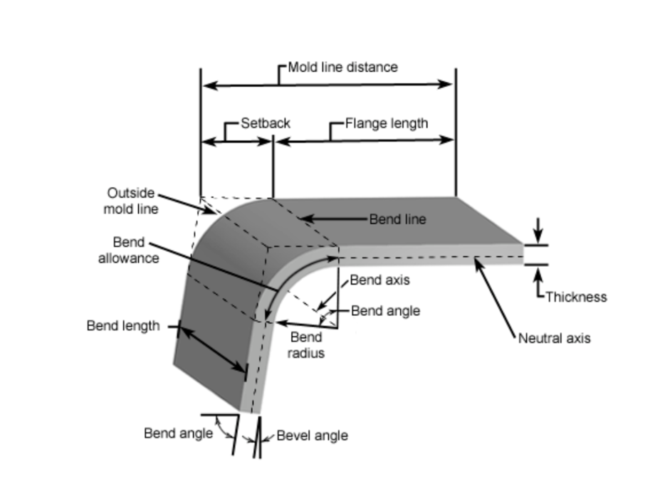
Sheet Metal Bend Radius Full Guide Chart
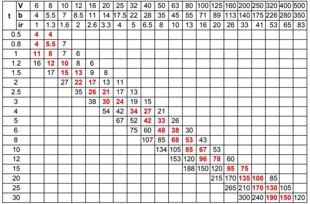
Sheet Metal Bending Design Tips, Bend Allowance, K Factor Fractory
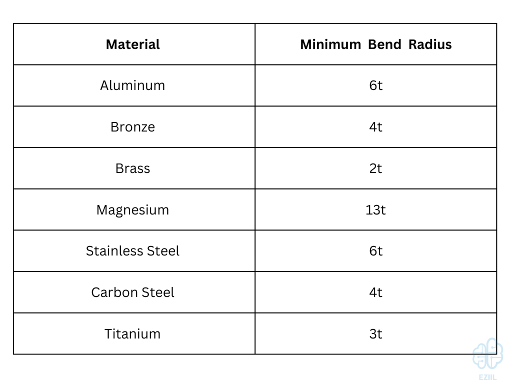
Sheet Metal Bend Radius Full Guide Chart
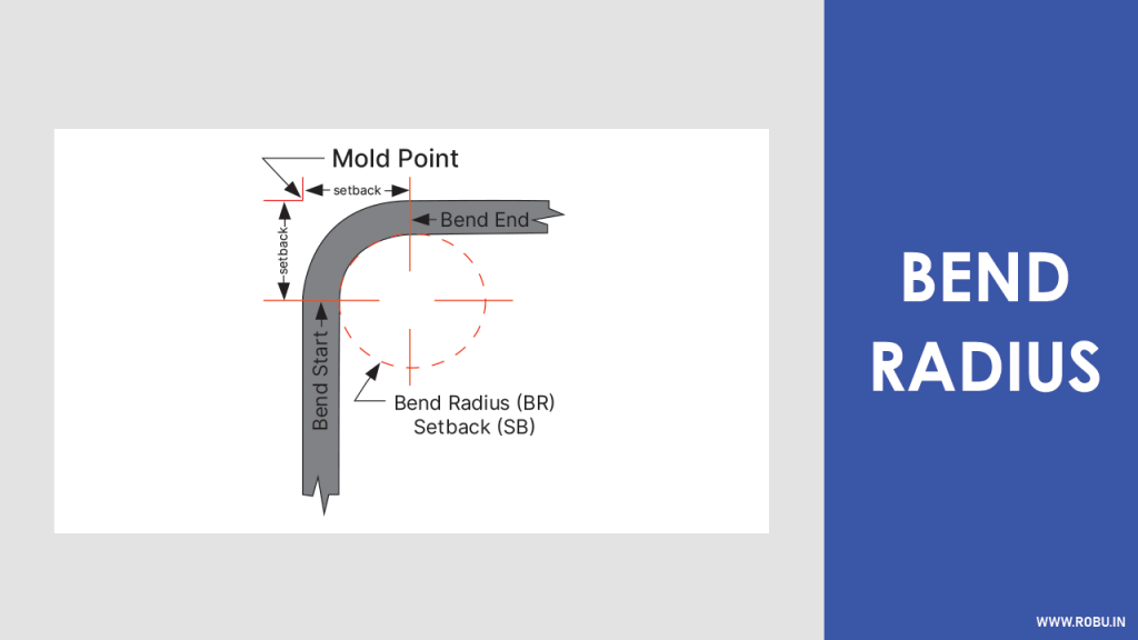
Sheet Metal Bend Radius Chart Pdf
Sheet Metal Bend Chart
Bend Radius Chart Sheet Metal
Bending Stainless Steel Tubing Effective Processes and Considerations
Sheet Metal Enclosure Design Key Enclosure Design Tips rapiddirect
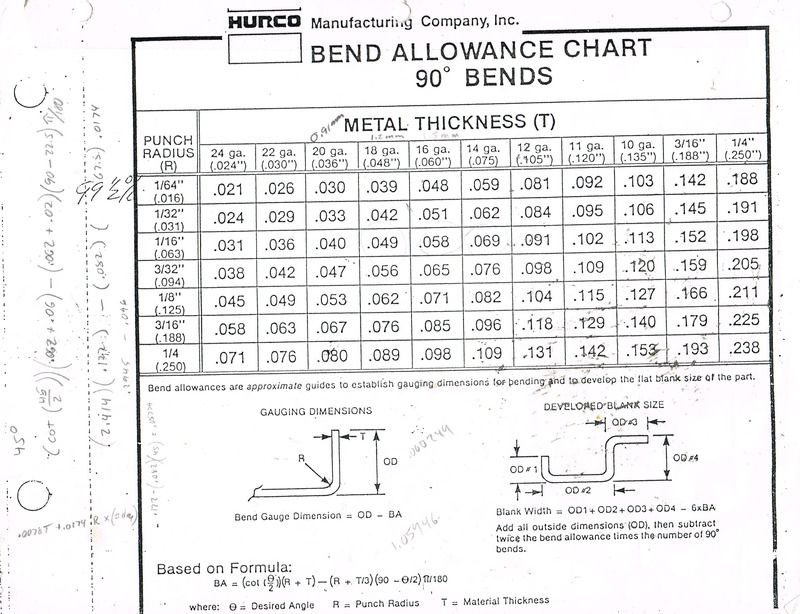
Sheet Metal Bends Radius for No +/ Factor
Web The Tables Below Show Bend Radii And Minimum Bend Sizes For Materials And Tooling Combinations Stocked By Protocase.
Minimum Flange And Minimum Hole.
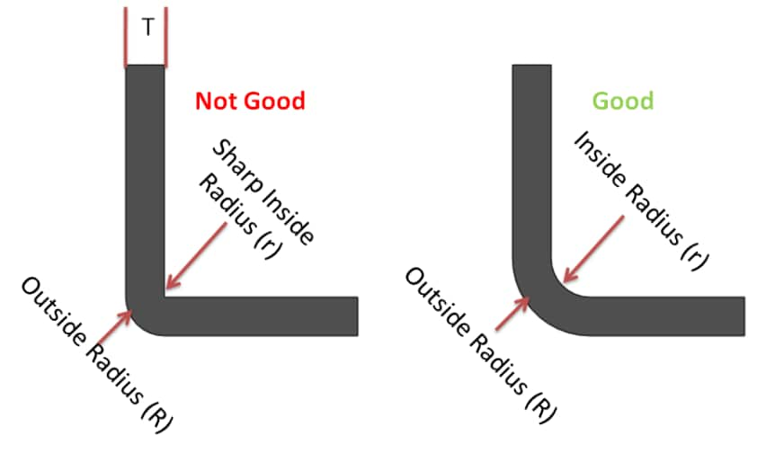
Web There Is A Minimum Bending Radius That Should Always Be Maintained In Sheet Metal Design Practices, And This Minimum Br Is Displayed As A Multiple Of The Specific Raw.
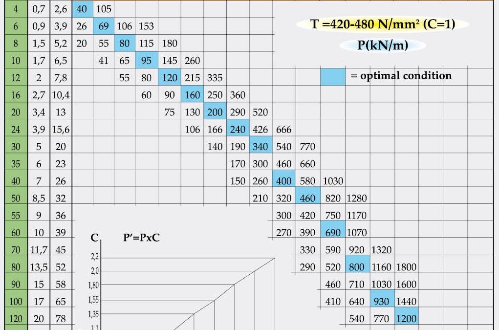
Web The Bending Force Table Below Helps You Identify The Minimum Flange Length B (Mm) And Inside Radii Ir (Mm) According To Material Thickness T (Mm).
Related Post: