A Section Line On A Drawing Shows
A Section Line On A Drawing Shows - It also allows you to show some structural detail. Web the general purpose or cast iron section line is drawn at a 45 degree angle and spaced 1/16 (1.5mm) to 1/8 (3mm) or more depending on the size of the drawing, but can be. Web a detailed explanation of section drawings: Web this video is in response to reviewing student work and seeing that many students do not remember how to draw a section line on their draftings. Web in reference to architectural drawing, the term section typically describes a cut through the body of a building, perpendicular to the horizon line. Web a section line on a drawing that indicates the geographical north is referred to as the north arrow. Web this section will cover the different types of section views, corresponding technical vocabulary, and help you determine which section view would best communicate. Web section lines on a drawing indicate a surface that has been cut or sliced in a section view. Used to indicate where the cutting plane cuts the material. What they are, where they are used, their different types, how to create them, and much more. Web a section line on a drawing is a line that indicates where a cutting plane has been placed to produce a sectional view of an object. Web a detailed explanation of section drawings: It also allows you to show some structural detail. Web this video is in response to reviewing student work and seeing that many students do not. Web a section line on a drawing is a line that indicates where a cutting plane has been placed to produce a sectional view of an object. Used to indicate where the cutting plane cuts the material. A section drawing is one that shows. In a section view, the object is shown as if it were cut along the cutting. Web a 'section drawing', 'section' or 'sectional drawing' shows a view of a structure as though it had been sliced in half or cut along another imaginary plane. Section lines are thin and the symbols (type of lines) are chosen according to the material of the object. Used to indicate where the cutting plane cuts the material. Web the general. A section drawing is one that shows. What they are, where they are used, their different types, how to create them, and much more. Web section lining is a method of representing internal features of an object in an engineering drawing. To illustrate where solid material be exposed by such a cut, section lining is. Web in reference to architectural. The section line is typically a. Web a 'section drawing', 'section' or 'sectional drawing' shows a view of a structure as though it had been sliced in half or cut along another imaginary plane. Web this video is in response to reviewing student work and seeing that many students do not remember how to draw a section line on their. Web the section line defines the extents of the section to extract from the building model. It also allows you to show some structural detail. The section line is typically a. What they are, where they are used, their different types, how to create them, and much more. Web section lining is a method of representing internal features of an. Web a 'section drawing', 'section' or 'sectional drawing' shows a view of a structure as though it had been sliced in half or cut along another imaginary plane. In a section view, the object is shown as if it were cut along the cutting plane line. Web section lines on a drawing indicate a surface that has been cut or. Used to indicate where the cutting plane cuts the material. In a section view, the object is shown as if it were cut along the cutting plane line. What they are, where they are used, their different types, how to create them, and much more. Web a 'section drawing', 'section' or 'sectional drawing' shows a view of a structure as. This northward orientation aligns with the geographic north. Web a 'section drawing', 'section' or 'sectional drawing' shows a view of a structure as though it had been sliced in half or cut along another imaginary plane. Web this section will cover the different types of section views, corresponding technical vocabulary, and help you determine which section view would best communicate.. In a section view, the object is shown as if it were cut along the cutting plane line. It also allows you to show some structural detail. To illustrate where solid material be exposed by such a cut, section lining is. Web the section line defines the extents of the section to extract from the building model. Web in reference. Section lines are thin and the symbols (type of lines) are chosen according to the material of the object. Web section lines on a drawing indicate a surface that has been cut or sliced in a section view. Used to indicate where the cutting plane cuts the material. Web this section will cover the different types of section views, corresponding technical vocabulary, and help you determine which section view would best communicate. A section line can be cut from any part of the. Web in reference to architectural drawing, the term section typically describes a cut through the body of a building, perpendicular to the horizon line. Web the general purpose or cast iron section line is drawn at a 45 degree angle and spaced 1/16 (1.5mm) to 1/8 (3mm) or more depending on the size of the drawing, but can be. What they are, where they are used, their different types, how to create them, and much more. It also allows you to show some structural detail. Web section lining is a method of representing internal features of an object in an engineering drawing. Section lines are bidirectional and you can specify the length and depth of the section. Web a section line on a drawing is a line that indicates where a cutting plane has been placed to produce a sectional view of an object. To illustrate where solid material be exposed by such a cut, section lining is. A section drawing is one that shows. The section line is typically a. Web a detailed explanation of section drawings: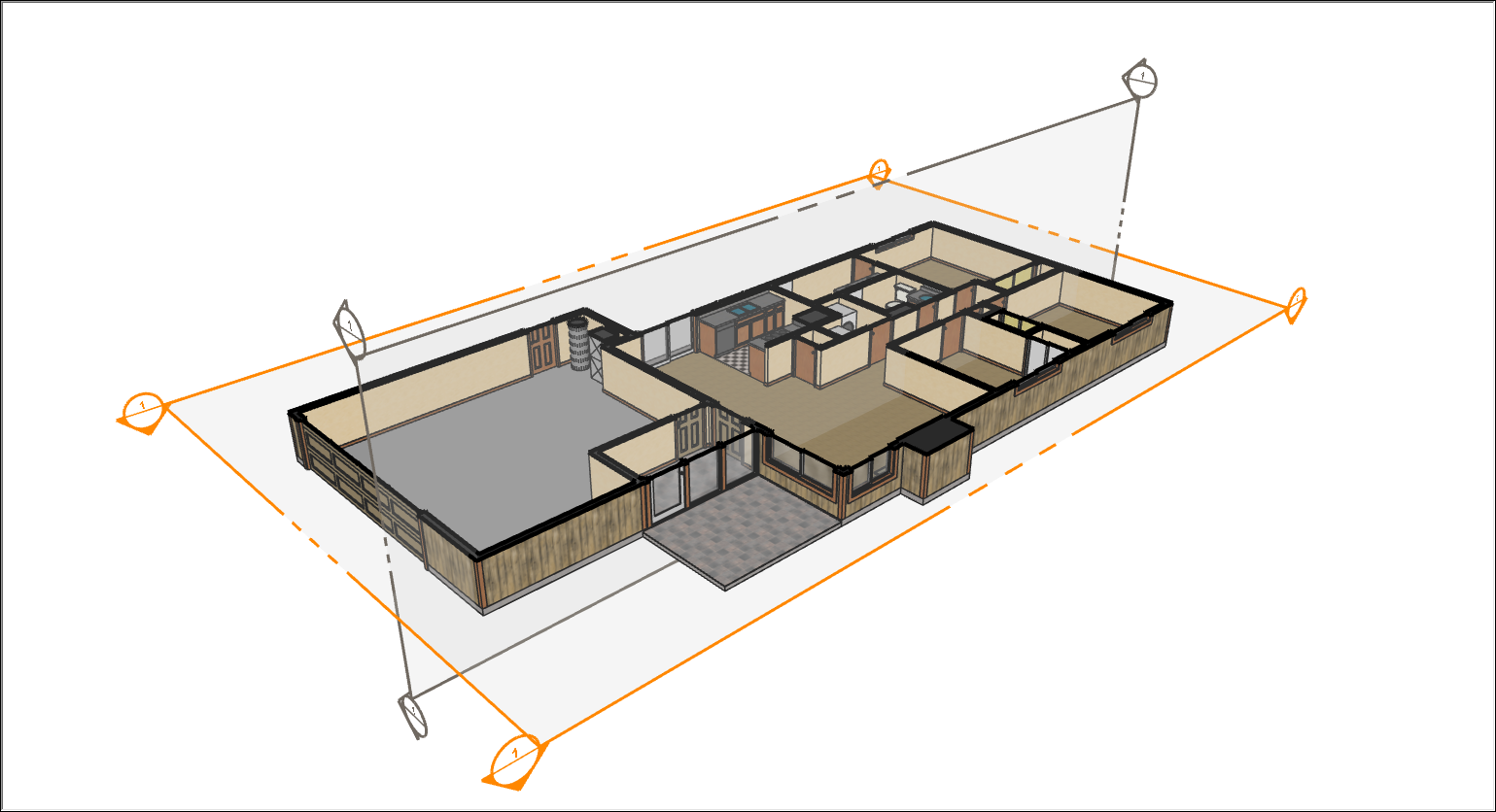
How to Show Section Cuts in Plan Drawing Davis Affire
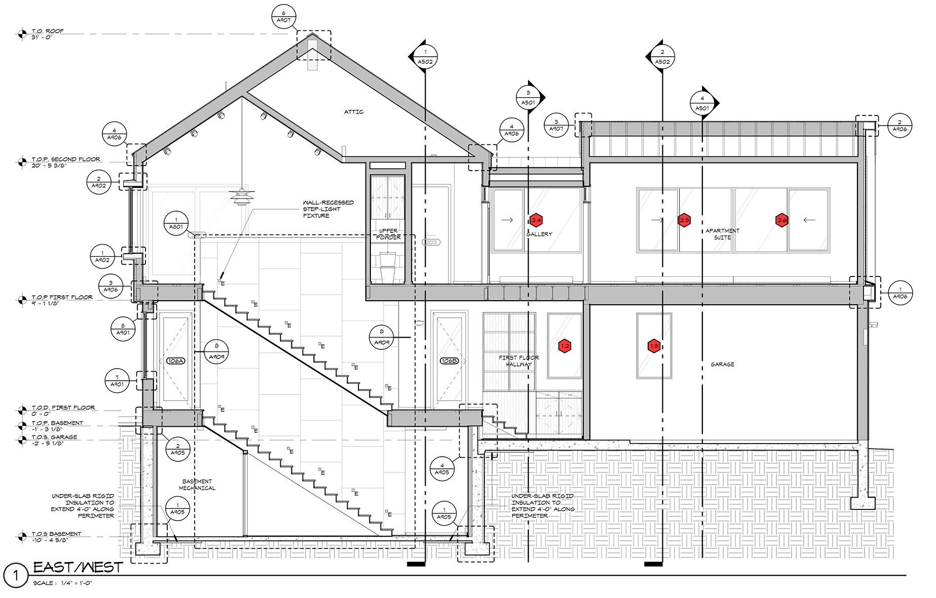
Section Drawing Architecture at Explore collection
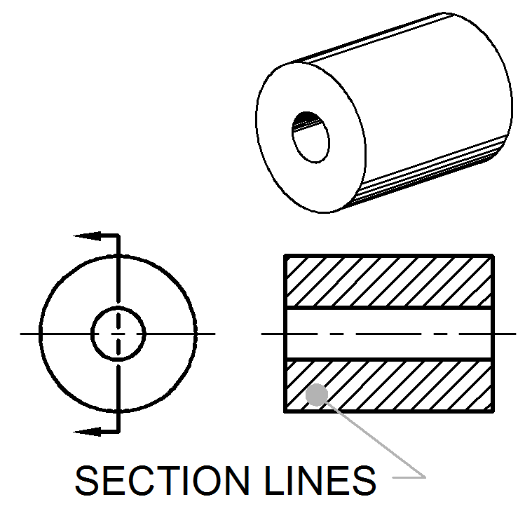
Section Lines ToolNotes

How To Draw Section And Elevation In Autocad Design T vrogue.co

34 Drawing a section line from a contour plan YouTube
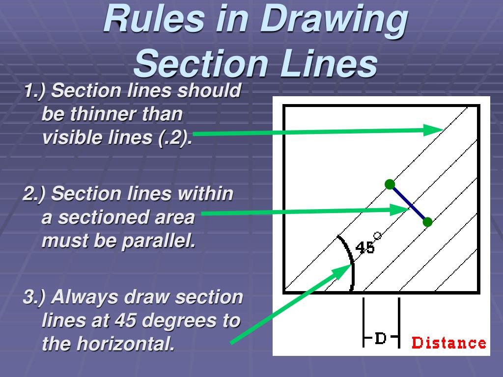
PPT SECTIONING PowerPoint Presentation, free download ID2709587

Full Sectioning Problem 1 Engineering Drawing 9.1 YouTube

SOLIDWORKS Section Jog Line Options for Drawing Views

Architectural Section Drawing
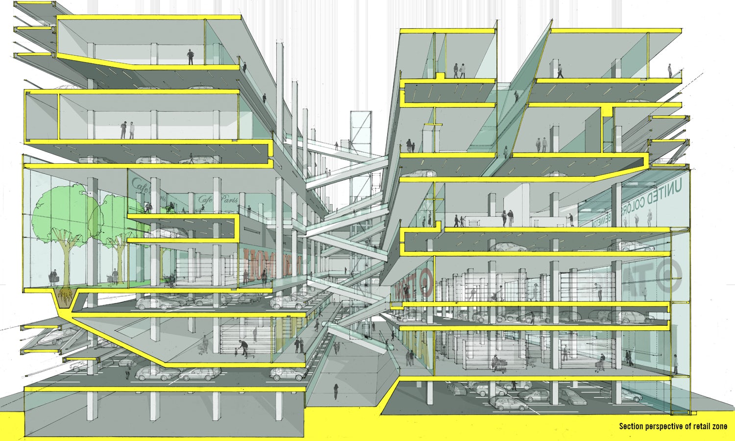
Architecture 101 What Is a Section Drawing? Architizer Journal
Web A Section Line On A Drawing That Indicates The Geographical North Is Referred To As The North Arrow.
Web The Section Line Defines The Extents Of The Section To Extract From The Building Model.
This Northward Orientation Aligns With The Geographic North.
Web A 'Section Drawing', 'Section' Or 'Sectional Drawing' Shows A View Of A Structure As Though It Had Been Sliced In Half Or Cut Along Another Imaginary Plane.
Related Post: