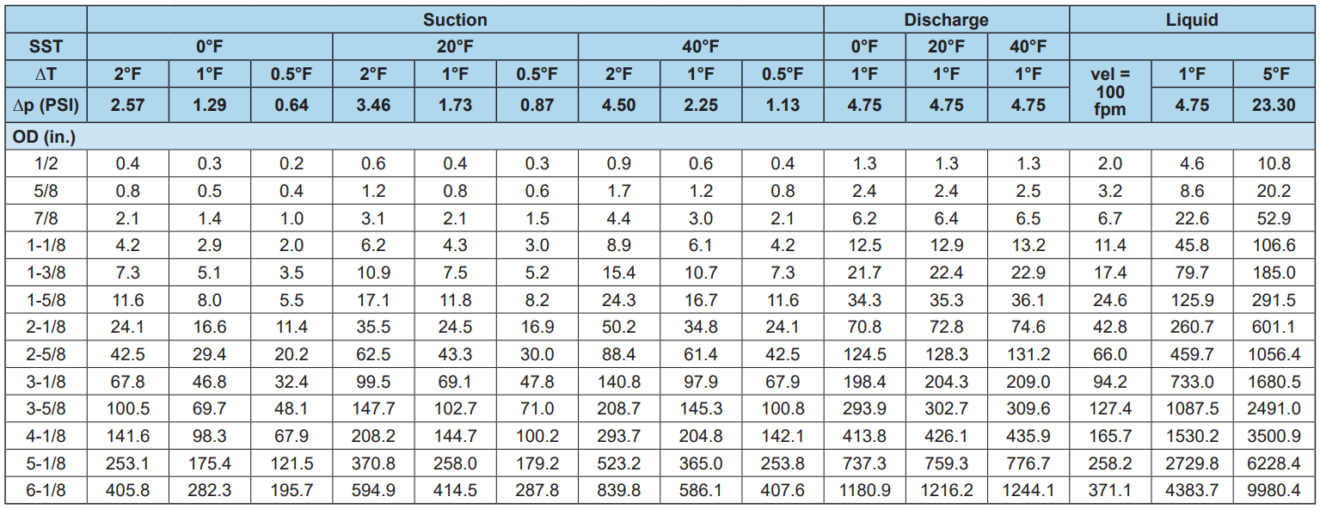
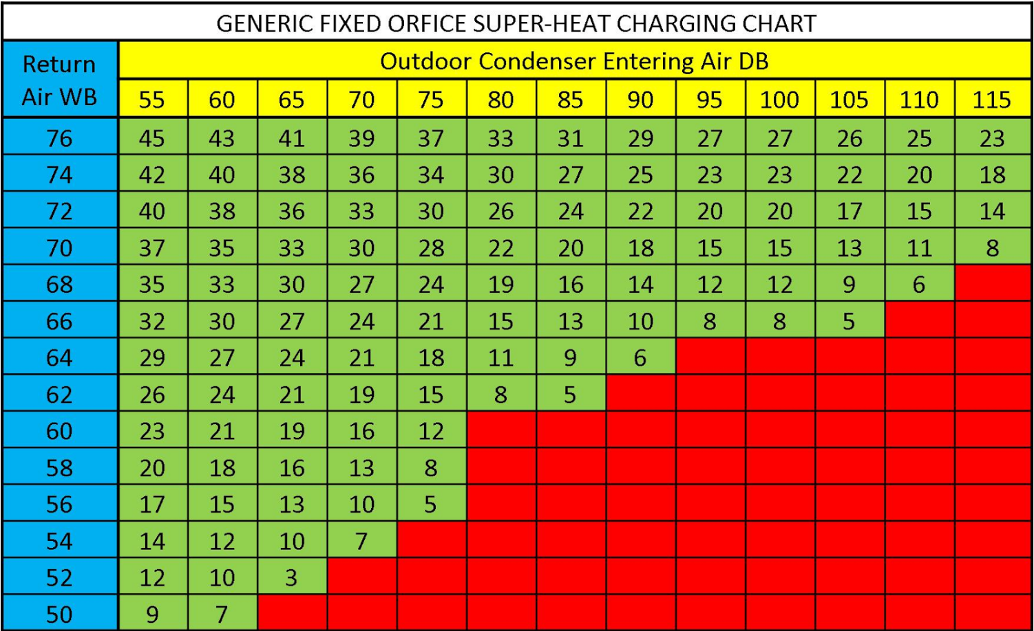
410A Refrigerant Pipe Sizing Chart
410A Refrigerant Pipe Sizing Chart - • provide adequate refrigerant flow to the evaporators, using practical refrigerant line sizes that limit pressure drop •. Web application dictates different line sizes due to pressure drop, refrigerant velocity constraints and/or line set lengths. Staying within these guidelines and charging to a. Web the piping design of any air conditioning system will affect the performance, reliability, and applied cost of that system. 9351−l9 revised july 30, 2018. Refer to dupont refrigerant expert, version 2.0 for actual velocities and pressure drops. Use it to determine the. For cooling systems where the in door and outdoor. It does not apply to industrial. Web piping guide for suva® 410a (eng) • equivalent length is actual length plus friction losses caused by fittings and accessories. Use it to determine the. Web design and fabrication guidelines. The design of refrigerant piping systems involves capacity. Web piping guide for suva® 410a (eng) • equivalent length is actual length plus friction losses caused by fittings and accessories. Web application dictates different line sizes due to pressure drop, refrigerant velocity constraints and/or line set lengths. Web application dictates different line sizes due to pressure drop, refrigerant velocity constraints and/or line set lengths. Use it to determine the. 9351−l9 revised july 30, 2018. Web these line sizing charts are based on a suction pressure drop equivalent to a 2°f change in saturation pressure and liquid line pressure drop of 5 psi. Refer to dupont refrigerant expert,. Web line sizing, routing, and component selection. Web design and fabrication guidelines. Staying within these guidelines and charging to a. • provide adequate refrigerant flow to the evaporators, using practical refrigerant line sizes that limit pressure drop •. Web these line sizing charts are based on a suction pressure drop equivalent to a 2°f change in saturation pressure and liquid. Web the piping design of any air conditioning system will affect the performance, reliability, and applied cost of that system. Web line sizing, routing, and component selection. Web piping guide for suva® 410a (eng) • equivalent length is actual length plus friction losses caused by fittings and accessories. Web new tables of the thermodynamic properties of freontm 410a refrigerant (ashrae. For cooling systems where the in door and outdoor. Web the liquid line sizing charts in this guideline have been developed based on a txv metering device on the indoor coil. Web r410a refrigerant piping guide. • provide adequate refrigerant flow to the evaporators, using practical refrigerant line sizes that limit pressure drop •. Web to size refrigerant piping. Web application dictates different line sizes due to pressure drop, refrigerant velocity constraints and/or line set lengths. Liquid lines should be sized as small as possible without exceeding the recommended. Web to size refrigerant piping. Web r410a refrigerant piping guide. Web r410a refrigerant piping guide • refer to dupont refrigerant expert, version 2.0 for actual velocities and pressure drops. Refer to dupont refrigerant expert, version 2.0 for actual velocities and pressure drops. • provide adequate refrigerant flow to the evaporators, using practical refrigerant line sizes that limit pressure drop •. • equivalent length is actual length plus friction. Within these guidelines, refrigeration operation is maintained while. Web piping guide for suva® 410a (eng) • equivalent length is actual length. It does not apply to industrial. Web r410a refrigerant piping guide • refer to dupont refrigerant expert, version 2.0 for actual velocities and pressure drops. Air conditioning equipment and heat pumps. Web r410a refrigerant piping guide. Web these line sizing charts are based on a suction pressure drop equivalent to a 2°f change in saturation pressure and liquid line pressure. • equivalent length is actual length plus friction. Web piping guide for suva® 410a (eng) • equivalent length is actual length plus friction losses caused by fittings and accessories. Web new tables of the thermodynamic properties of freontm 410a refrigerant (ashrae designation: Figure 5 illustrates an example of a (4) tta/twa blower coil split system component arrangement. Web the liquid. Figure 5 illustrates an example of a (4) tta/twa blower coil split system component arrangement. Web new tables of the thermodynamic properties of freontm 410a refrigerant (ashrae designation: • equivalent length is actual length plus friction. Web refrigerant piping design goals a common goal is to size the suction, hot gas and liquid lines for about 1fº pressure drop at. Web the philosophy in designing a refrigerant piping system can be summed up as follows: Air conditioning equipment and heat pumps. The design of refrigerant piping systems involves capacity. Refrigerant cylinders are painted a. Web piping guide for suva® 410a (eng) • equivalent length is actual length plus friction losses caused by fittings and accessories. Within these guidelines, refrigeration operation is maintained while. Web line sizing, routing, and component selection. For cooling systems where the in door and outdoor. • provide adequate refrigerant flow to the evaporators, using practical refrigerant line sizes that limit pressure drop •. Figure 5 illustrates an example of a (4) tta/twa blower coil split system component arrangement. It does not apply to industrial. 9351−l9 revised july 30, 2018. Web these line sizing charts are based on a suction pressure drop equivalent to a 2°f change in saturation pressure and liquid line pressure drop of 5 psi. Use it to determine the. Liquid lines should be sized as small as possible without exceeding the recommended. Staying within these guidelines and charging to a.
R410a Refrigerant Line Sizing Chart

R410a Refrigerant Line Sizing Chart
8 R410A Refrigerant Pipe Sizing Charts 2k23

Refrigerant Piping part2 Refrigeration HVAC/R & Solar

8 R410A Refrigerant Pipe Sizing Charts 2k23

8 R410A Refrigerant Pipe Sizing Charts 2k23

Refrigerant Pipe Size Chart R410a Labb by AG

410a Line Set Sizing Chart

Refrigerant Pipe Sizing Chart For 410a

R410a Refrigerant Line Sizing Chart
Web Refrigerant Piping Design Goals A Common Goal Is To Size The Suction, Hot Gas And Liquid Lines For About 1Fº Pressure Drop At Design Capacity.
Web Design And Fabrication Guidelines.
Web The Piping Design Of Any Air Conditioning System Will Affect The Performance, Reliability, And Applied Cost Of That System.
Only Qualified Personnel Should Install And Service The Equipment.
Related Post:
